This is my first working tube amp. I pulled it from a old readers digest portable record player. I built a dim bulb tester and recapped it before hooking it up to my pioneer bs22 speakers. Wow am i impressed!!
Anyway...now what? Id love to remove the tone controls. And maybe improve the circuit somehow. But, i also want to keep it simple...
Thanks in advance
Anyway...now what? Id love to remove the tone controls. And maybe improve the circuit somehow. But, i also want to keep it simple...
Thanks in advance
Some people know how to modify an amp without a schematic (because they have the amp in front of them).
For those who do not have the amplifier in front of them, they may know how to modify an amp if they have the schematic.
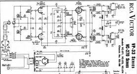
Please post the schematic.
For those who do not have the amplifier in front of them, they may know how to modify an amp if they have the schematic.
Please post the schematic.
Remember, people are cheap and goods are inexpensive. That is (in the correct sense) a very cheap setup. You have 2 single ended channels operating out of phase so that bass can be summed to push/pull mono.
The O/P transformers should be replaced, if decent wide range speakers are to be employed. What's in situ are close to junk. 😡 The stereo pair of transformers can't handle bass and the mono transformer can't handle anything but bass.
I'm providing the schematic of a Magnavox console amp that uses the same signal tube complement, but doesn't have the objectionable tone controls. Volume controls have to be added to the "Maggotbox" setup. This is a suitable, modest cost, O/P transformer.
Attachments

I removed everything after the output transformers. I had the feed going directly to my bookshelf speakers. Thanks for the help. Im probably going to rewire it to the specs you provided. Any hints on what size transformers i should be looking for?
The Magnavox setup contains a GNFB loop. Magnetic headroom is essential in such circuitry. You would be hard pressed to find anything remotely suitable, at lower cost, than the previously linked Edcor product. That part will require some bandwidth limiting at the unit's I/P. Making the setup's 3 dB. down point at approx. 30 Hz. should not be an issue, as few bookshelf speakers go that low.
FWIW, the spec. sheet for your Pioneer speakers indicates 55 Hz. as the low freq. limit. The 5 or so WPC produced by 2X SE 6BQ5s is insufficient for reproducing wide dynamic range music.
Because the Pioneer speakers don't go deep, you may not be able to hear the bass deficiency of the RCA "iron".
FWIW, the spec. sheet for your Pioneer speakers indicates 55 Hz. as the low freq. limit. The 5 or so WPC produced by 2X SE 6BQ5s is insufficient for reproducing wide dynamic range music.
Because the Pioneer speakers don't go deep, you may not be able to hear the bass deficiency of the RCA "iron".
Note:
Both of those amplifiers are using output transformers in a special mode.
The screen resistors connect at one end of the primary, and the plate is at the other end of the primary, with B+ somewhere in the middle.
That is Positive feedback.
Ultra Linear is when the plate is at one end, B+ is at the other end, and the screen resistor is somewhere at the middle.
Try switching the screen resistors and B+ connections.
If that oscillates, then the schematics are wrong.
It's a hum-canceling connection - transformer tap cost less than bigger or more filter caps. Since the 5Y3 is running well below maximum voltage and current, it can handle the 80 uF filter cap. DON'T increase it unless you change to a solid state rectifier!
RCA had good transformers in the console amps I've seen. This one doesn't have a bass channel transformer as some do - bass channel is combined through the crossover network (IN phase). Negative feedback will definitely help flatten frequency response (including any resonant peaks of the speaker).
As-is, without feedback, the treble response was probably excessive due to rising impedance of speaker with frequency. Hence the "cut" only treble control... the bass control will have ZERO effect unless it's driven by a ceramic phono cartridge. The balance control would be worse than useless inside the feedback loop so it has to go (and feedback will make the channels match anyway!). Loudness compensation can be removed by removing the components at the control taps, or the control can be removed entirely if you have another level control in the system (Although all controls are essentially out of the circuit at the "max" end). Some of these controls are also serving as grid returns - 470K resistors can replace that function.
The Magnavox circuit shows how to add negative feedback - if it oscillates, reverse the primary or secondary of the output transformer.
Last edited:
Im probably gonna order the transformers from the link you sent me Eli. Thank you!
Tom, you are right on the tone controls. I could slightly adjust the treble but, the bass control did nothing.
Im in no hurry. I have a ton to learn before i really dig into this thing. I was so impressed with the way it sounded as is. That i am thinking of completly rewiring it into a diffrent/ better topology. Id like to reuse as much of the components that i can.
Ya i know driving a set of cheap pioneer speakers with a tube amp ripped from a old record player doesnt seem like much. But, to me..those pioneer speakers are the best ive ever owned. This tube amp that i got for free, is my stepping stone into a technology that not many people care to learn.
Id like to reuse as much of the components that i can.
The sheet metal, power transformer, tubes (if still strong), and tube sockets can be recycled.
Carbon composition resistors drift in value and become noisy, over time. Electrolytic capacitors literally dry out, with the passing of time. Waxed paper capacitors electrically leak. Therefore, the above parts get "tossed". Bad 'lytics can cause the destruction of costly magnetics.
 Don't be penny wise and pound foolish!
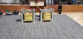
Audio transformers are more than bit of "black art". Interleaving to obtain good bandwidth is the norm. A typical problem is keeping inductance up, for bass performance, while avoiding excessive winding capacitance, which degrades HF performance. 
IIRC, member Tony Tecson winds his own "iron". You might PM him.
IIRC, member Tony Tecson winds his own "iron". You might PM him.
I wonder if its possible to wind my own transformers? I have 3 identical transformers / inductors from a ultrasonic generator. I know there is a ton of math/ finding the proper materials but, why not try?
You absolutely *can* wind your own transformers, but it's another large step to take. Many (most, really) folks who build their own amplifiers these days buy transformers, just like they buy capacitors and resistors.
It's about equally challenging to design a good audio transformer as to design the rest of the amplifier. So: possible, but maybe not for your very first project. And you can always leave chassis room to change to your new transformers later.
All the best fortune,
Chris
Tom Bavis,
Good catch! Post #8.
Both the schematics have hum cancelling output transformer connections.
But, that means they are the opposite of Ultra Linear. They have local positive feedback, instead of local negative feedback.
They have very high plate resistance.
Global negative feedback should be employed.
The second schematic does have global negative feedback.
That example could be used.
Using the old transformers would be better to use true pentode mode with negative feedback, and improved B+ filtering.
Or to rewire the screen and B+ connections, and use Ultra Linear, again better B+ filtering would be required.
Those ratios would almost certainly require some global negative feedback too.
Eli Duttman,
Post # 13, These are Single Ended amplifiers, the transformers need to be air gapped.
interleaving the laminations for push pull is a good idea . . . but not a good idea for an SE output stage.
I just finished an amplifier that uses an Edcore transformer. I got it for a song, it was a custom one for a commercial product.
I was impressed by the quality, it is the first Edcore model I have used.
But I do like the Electra Print SE and One Electron SE transformers I have already used.
The Edcore model I have is for push pull; but what I see with that one, makes me interested in trying an Edcore SE transformer too.
Last edited:
These are Single Ended amplifiers, the transformers need to be air gapped.
interleaving the laminations for push pull is a good idea . . . but not a good idea for an SE output stage.
I wasn't talking about the laminations. I was commenting on the coil winding techniques. SE lamination stacks definitely need air gaps.
Eli,
You are correct.
What was I thinking?
Well, I have re-stacked laminations from PP to SE to PP.
That was on my mind.
I have never wound the coils, but yes, interleaving is important; SE and PP.
You are correct.
What was I thinking?
Well, I have re-stacked laminations from PP to SE to PP.
That was on my mind.
I have never wound the coils, but yes, interleaving is important; SE and PP.
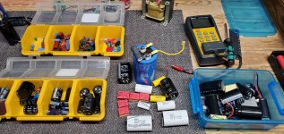
Finding a simple circuit for a solid state amp is much easier for me. Can anyone point me to a specific post or circuit diagram that would work with the tubes i have? I dont mind tracking down new resistors and capacitors. I have a pretty healthy stock of stuff i save. I use a LCR meter to check capacitors/dissipation and q factor. Its no problem to buy a few resistors and new capacitors. Lol lets call it a junkyard build.
Attachments
There are lots of simple vacuum tube amplifier schematics, plans, and hints and kinks discussions about those particular amplifiers, etc.
What tubes do you have?
Just those in the amplifier in post #1?
You may need to get other tube types, or you may not.
If the amp you have works well with your speakers, then there are lots of simple amplifier schematics that have that much power out.
What tubes do you have?
Just those in the amplifier in post #1?
You may need to get other tube types, or you may not.
If the amp you have works well with your speakers, then there are lots of simple amplifier schematics that have that much power out.
Last edited:
If you're going to add global feedback (that includes the output transformer secondary) you will want to use the specific output transformer specified in the schematic. It has to do with tuning the amp for best performance, which is output transformer specific.
Otherwise, if you don't want global feedback (many SE fans do not) then you might start your learning journey by looking at the RH topology. (Google "RH84 tube amplifier".) This topology uses plate to plate feedback (output stage to driver stage). Or if you have an output transformer with a UL tap, you could try an approach where feedback is taken from the UL tap to the plate of the driver. If this is your first build, I might suggest the RH topology to get you going.
However, I prefer a little global feedback even in SE amps, but that's just me. Also see my PM to you for some additional thoughts.
Last edited:
- Home
- Amplifiers
- Tubes / Valves
- Rca rs188