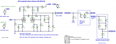
I have created a spice simulation using the RIAA phono preamp from the RCA tube manual.
Included is reverse RIAA network, the Jung-Lipshitz Improved inverse RIAA
Network (From original TAA article).
Two signal generators or on the sim a 1kHz sine wave and a 1kHz square wave.
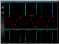
The waveforms show a square wave fed into the preamp, the output of the RIAA and the restored
square wave out of the inverse network.
I'm certain a better spice model for the tube could be used.
Please feel free to improve on this work and repost.
The original RCA component designators were used.
https://hifisonix.com/wordpress/wp-content/uploads/2016/12/Accurate-Inverse-RIAA.pdf
Ken K
Included is reverse RIAA network, the Jung-Lipshitz Improved inverse RIAA
Network (From original TAA article).
Two signal generators or on the sim a 1kHz sine wave and a 1kHz square wave.
The waveforms show a square wave fed into the preamp, the output of the RIAA and the restored
square wave out of the inverse network.
I'm certain a better spice model for the tube could be used.
Please feel free to improve on this work and repost.
The original RCA component designators were used.
https://hifisonix.com/wordpress/wp-content/uploads/2016/12/Accurate-Inverse-RIAA.pdf
Ken K
Attachments


Eli Duttman would suggest a mosfet follower to buffer the load of the volume control.
Attachments
Last edited:
Hi Rayma thank you for your reply.Eli Duttman would suggest a mosfet follower to buffer the load of the volume control.
As you suggested using something to lower the output impedance would be required in most applications.
My aim was to simulate the RCA circuit as it was originally produced by RCA as a tribute to them.
The Inverse RIAA network and buffer in the spice simulation are of special interest as they can be used with any RIAA preamp to test for compliance with RIAA equalization. In the days before all the sophisticated equipment we now have, all that was required to test a preamp was a suitable square wave generator. a reverse RIAA network and an oscilloscope. I used to have a reverse RIAA network about and should make a new one, very handy if designing or building RIAA preamps.
Tubekwk: Reading your interesting post I noticed in the LTspice schematic the use of labels like "output RIAA" and" ref RIAA".
Never used this kind of labeling in LTspice and I am interested how to do this in the way you are doing this.
Is it possible to publish your .asc circuit diagram here?
Thanks in advance,
Joe.
Never used this kind of labeling in LTspice and I am interested how to do this in the way you are doing this.
Is it possible to publish your .asc circuit diagram here?
Thanks in advance,
Joe.
Hi Joe
The .asc file was uploaded with the images, if you have trouble downloading it I will re upload it.
Go to the net name icon at the top of LTspice it is a capital A in a rectangle icon.
If you give a name to a node it will automatically link to wherever you place a copy.
It automatically names any "oscilloscope" traces with the node name. No spaces are allowed in node names so I use an under score.
I will reattach the **.asc file here.
BTW you may need to change the font size.
Ken K
Attachments

Wow, no sorry.. big WOW !! @Tubewkw
I have a simple diy ecc83 phono amp sounding smooth and (too) meaty which output is noisy..
I was looking into the RCA material and its variations (including Eli Duttman's of course) to improve it.. lots of food for thoughts here, and getting going noobs with Spice simulation is a very big plus, thanks a lot for posting this!
Thank you very much Tubekwk, much appreciated!Tubekwk: Reading your interesting post I noticed in the LTspice schematic the use of labels like "output RIAA" and" ref RIAA".
Never used this kind of labeling in LTspice and I am interested how to do this in the way you are doing this.
Is it possible to publish your .asc circuit diagram here?
Thanks in advance,
Joe.
And I have to confess that, although I also use the "label" in my LTspice schematings, after years of use I never noticed that you also can define its "Port Type" !!

I simply put a name in the box and then connect it to a node.
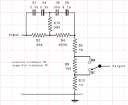
I myself are using a slightly modified inverse RIAA network, the one which Merlin Blencowe published in his book "Designing High-Fidelity Tube Preamps".
Which is on page 344/345 of that book. This because you do not have to use then rare capacitor values. I do not give that circuit diagram because I do not want to violate
copyrights. So first I have to pm MB for his O.K.
Perhaps you are correct but I prefer to "better safe than sorry" though.Circuits are not copyrightable, only circuit diagrams. If you redraw it you are not violating copyright.
Have sent a pm to Merlin Blencowe but I did not (yet) take the trouble to respond......
Correction! Typo error : "I" must be "He" .Perhaps you are correct but I prefer to "better safe than sorry" though.
Have sent a pm to Merlin Blencowe but I did not (yet) take the trouble to respond......
here the MB circuit diagram. For further explanation see his above mentioned book on pages 344 & 345.There is no 'perhaps' about it.
Attachments
FYI, you can make a perfect reverse RIAA network in LTSpice using a controlled source with a Laplace expression.
Edit: that's a silly remark, as I don't think those work in transient analyses.
Edit: that's a silly remark, as I don't think those work in transient analyses.
Attached is an inverse RIAA source using a voltage controlled voltage source. It is a mathematically precise representation of the RIAA curve.
The factor "n" normalizes the 1 KHz output level to match whatever value is given to the SIGNAL source. For example, if you want the RIAA signal level to be 1 mV peak at 1 KHz, set SIGNAL to 1 mV.
The "enhanced" option incorporates the so-called Neumann 3.18 microsecond time constant. While that has pretty much been dismissed as unnecessary, I've included the formula in case you want to simulate the response of a phono preamp that did implement it. Here is a link to an article that discusses the origins of the Neumann time constant and why most phono preamps don't implement it.
https://www.stereophile.com/features/cut_and_thrust_riaa_lp_equalization/index.html
This model works for both AC and transient analysis, although the sine wave output isn't as pure as one would like.
Attachments
The main advantage is that you do not have to use rare capacitor values due to the insertion of that 680 Ohm resistor.here the MB circuit diagram. For further explanation see his above mentioned book on pages 344 & 345.
- Home
- Amplifiers
- Tubes / Valves
- RCA phono preamp and reverse RIAA