Let me start with an introduction. A couple semesters ago I took an electromagnetics class where we discussed heavily the matter of transmission lines - coaxial transmission lines of course being apart of that. At the time I didn't realize the significance of the principles we were being taught, and so I slacked off. I now am starting to realize the importance of what was being professed in my recent quest to figure out what exactly makes a high quality audio cable.
I have found that maybe 5% of online resources cite actual electrical/scientific properties for the reasoning behind why their cable (bought or manufactured) is better. ['ooh this one sounds "brighter"', 'ooh this one's better for bass because SILVER', etc.] While I could do a subjective ear test between the cables I own to see which one I personally think sounds the best, this contradicts who I am. I need to know which is electromagnetically, scientifically the best. And by best, I mean has the flattest response.
Now, it seems one thing we can all agree on is that the most influential aspect of analog interconnects is conductivity. And therefore, its inverse, impedance. People seem to diverge after that.
I researched the question "RCA coax vs twisted pair" (as these are basically the only forms of RCA cable on the market), and returned with the result that twisted pair is good for balanced lines - because it only has good magnetic rejection, and coaxial is good for unbalanced - because it is shielded. This was good; the explanations matched the technology, but something kept nagging me. Coax has a characteristic impedance. The characteristic impedance is good for high frequencies, but at which frequency does it stop becoming valid? Surely not audio frequencies?
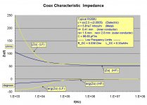
This is when I found what I was looking for... or so I think (this is where I open the topic for debate). The RCA cable I bought for my car application a while ago was RG58U coax rated from Monoprice, so this was a good spec to research. [View Image]
This is an analysis using accurate equations for coaxial impedance - coincidentally for the same type of cable I bought (some slight variations may occur). Important to notice would be the trend of parabolic regression at low frequencies. This chart only shows 1kHz to 20kHz in respect to audio frequencies, but one can see approximately a +6dB gain from 1k to 10k in this simulation plot. It is by this, that I am adamant that twisted pair is the best route for a flat response, and shielded twisted pair if the capacitance can be kept under a reasonable value, such as 100pF.
Audio gurus, Please tell me if I am missing anything.
I have found that maybe 5% of online resources cite actual electrical/scientific properties for the reasoning behind why their cable (bought or manufactured) is better. ['ooh this one sounds "brighter"', 'ooh this one's better for bass because SILVER', etc.] While I could do a subjective ear test between the cables I own to see which one I personally think sounds the best, this contradicts who I am. I need to know which is electromagnetically, scientifically the best. And by best, I mean has the flattest response.
Now, it seems one thing we can all agree on is that the most influential aspect of analog interconnects is conductivity. And therefore, its inverse, impedance. People seem to diverge after that.
I researched the question "RCA coax vs twisted pair" (as these are basically the only forms of RCA cable on the market), and returned with the result that twisted pair is good for balanced lines - because it only has good magnetic rejection, and coaxial is good for unbalanced - because it is shielded. This was good; the explanations matched the technology, but something kept nagging me. Coax has a characteristic impedance. The characteristic impedance is good for high frequencies, but at which frequency does it stop becoming valid? Surely not audio frequencies?
This is when I found what I was looking for... or so I think (this is where I open the topic for debate). The RCA cable I bought for my car application a while ago was RG58U coax rated from Monoprice, so this was a good spec to research. [View Image]
This is an analysis using accurate equations for coaxial impedance - coincidentally for the same type of cable I bought (some slight variations may occur). Important to notice would be the trend of parabolic regression at low frequencies. This chart only shows 1kHz to 20kHz in respect to audio frequencies, but one can see approximately a +6dB gain from 1k to 10k in this simulation plot. It is by this, that I am adamant that twisted pair is the best route for a flat response, and shielded twisted pair if the capacitance can be kept under a reasonable value, such as 100pF.
Audio gurus, Please tell me if I am missing anything.
Attachments
If you took a class in electromagnetics, you should also have found out that with the frequencies and lengths we are using for analog audio, the transmission line theory generally does not apply, rather we can look upon the problem as a strictly lumped R-L-C circuit, which of course can have its impact on the sound, given some akward combinations of pre-, power amplifiers and to some extent, also loudspeakers.
Even for digital audio, you would need some length of cables to really justify the T-line theory. Correct termination is really of higher importance in these cases.
Even for digital audio, you would need some length of cables to really justify the T-line theory. Correct termination is really of higher importance in these cases.
If you took a class in electromagnetics, you should also have found out that with the frequencies and lengths we are using for analog audio, the transmission line theory generally does not apply, rather we can look upon the problem as a strictly lumped R-L-C circuit, which of course can have its impact on the sound, given some akward combinations of pre-, power amplifiers and to some extent, also loudspeakers.
Even for digital audio, you would need some length of cables to really justify the T-line theory. Correct termination is really of higher importance in these cases.
Why then, is there an equation for low frequencies of coax transmission lines including R & C?
EDIT:
Okay, I understand now. It's the length that's important. Transmission Line Theory works based off an infinite length. This site helped me out: https://www.allaboutcircuits.com/te...nt/chpt-14/long-and-short-transmission-lines/
Attachments
Last edited:
Transmission Line Theory works based off an infinite length.
If the wavelength of the signal in the cable is small compared to the cable length,
then the TL equations are needed. Otherwise lumped parameters can be used,
which is the case for audio frequencies, since their electrical wavelengths in the cable
are over 10E5 meters.
Last edited:
> a +6dB gain from 1k to 10k
What means "gain"?
Certainly not transfer function amplitude rise.
Being a dumb lumped-constants man (at least inside the home), I see some hundreds of Ohms feeding ~~10K loads. I do not have to care if this alleged impedance is 50r or 250r. Zero dB loss for all practical purpose.
And as you and Rayma now point out, the characteristic impedance is for an infinite length, which means many wavelengths, but home-long cables at audio wavelengths are super-short.
There are other effects which matter beyond a mile. Not Our Problem.
> "RCA coax vs twisted pair"
Short unbalanced lines in benign places can just use coax.
But this means the wrap is doing two things: signal return and shielding.
In adverse conditions, you use STP, signal return on an inside conductor, the outside shield connected only at one end.
Because of the many-many other ground paths in real stereo systems, this is not always best.
It is very rare that a all-in-one-room hi-fi needs anything but coax. And it is cheaper.
....... the outside shield connected only at one end.
........
I'd guess if one wanted to ensure that there are no stray ( non signal !) currents in the ground line of an unbalanced system , we could use a shielded balanced cable. Use the two inner wires for signal and ground and connect one end of the ground wire to the outer shield. The question would arise , which end to connect to the shield? Wouldn't it be the end that needs to be closest to ground like the input end ?
Do we get unbalanced cable with TWO shields and insulated from each other ?
from another Thread today:In an unbalanced interconnect system there will be stray currents, there's no way around it. The question is, do you want those stray currents running thru a heavy braided shield or a small signal wire? That's why a coax cable with a heavy braided shield is best.
Connect the shield to the enclosure.
If the return signal uses the shield, then connect it to the signal return terminal at both ends.
In general the enclosure is NOT connected to the signal return. That means that the shield of a coaxial cable is NOT connected to the enclosure, unless the schematic requires that for the circuit to work.
When the shield is separate from the two signal cores, then the shield is NOT connected to Signal Return, instead the separate shield is connected to the enclosure.
The Safety Earth is a separate issue. Don't confuse that issue by trying to attach audio thinking to it.
No. The most influential thing for an analogue audio interconnect is capacitance.treyus30 said:Now, it seems one thing we can all agree on is that the most influential aspect of analog interconnects is conductivity. And therefore, its inverse, impedance.
Yes, around high audio frequencies or a bit higher is where a cable can begin to behave like its naive RF model. Fortunately, almost all audio interconnects are sufficiently short that this is not a problem. Twisted pair has a characteristic impedance too, of course.I researched the question "RCA coax vs twisted pair" (as these are basically the only forms of RCA cable on the market), and returned with the result that twisted pair is good for balanced lines - because it only has good magnetic rejection, and coaxial is good for unbalanced - because it is shielded. This was good; the explanations matched the technology, but something kept nagging me. Coax has a characteristic impedance. The characteristic impedance is good for high frequencies, but at which frequency does it stop becoming valid? Surely not audio frequencies?
Quite irrelevant to a short audio cable.This chart only shows 1kHz to 20kHz in respect to audio frequencies, but one can see approximately a +6dB gain from 1k to 10k in this simulation plot. It is by this, that I am adamant that twisted pair is the best route for a flat response, and shielded twisted pair if the capacitance can be kept under a reasonable value, such as 100pF.
No. Transmission line theory is needed when the cable is a significant fraction of a wavelength - having taken into account the wavelength in the cable, which may be different from wavelength in air/vacuum.Why then, is there an equation for low frequencies of coax transmission lines including R & C?
EDIT:
Okay, I understand now. It's the length that's important. Transmission Line Theory works based off an infinite length. This site helped me out:
Anyway, keep asking questions. Unlike many audio people, you probably have enough background knowledge in the relevant physics to understand the answers.
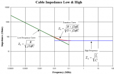
Audio cables have a characteristic impedance, but it is not the sqrt(L/C) value which is just an RF approximation. For audio the characteristic impedance is higher and reactive, because it is dominated by sqrt(R/jwC). Fortunately for short cables it can be ignored, because it would be difficult to provide an appropriate termination.
In any case, it's not a single value. Near DC it's almost an open connection and slowly lowers to the RF value at about 100 kHz.Audio cables have a characteristic impedance, but it is not the sqrt(L/C) value which is just an RF approximation. For audio the characteristic impedance is higher and reactive, because it is dominated by sqrt(R/jwC). Fortunately for short cables it can be ignored, because it would be difficult to provide an appropriate termination.
I'd guess if one wanted to ensure that there are no stray ( non signal !) currents in the ground line of an unbalanced system , we could use a shielded balanced cable. Use the two inner wires for signal and ground and connect one end of the ground wire to the outer shield. The question would arise , which end to connect to the shield? Wouldn't it be the end that needs to be closest to ground like the input end ?
Would this cable fit the bill?

Or this?

https://www.tubedepot.com/products/mogami-w2582-low-cost-high-performance-superflexible-balanced-microphone-cable
No. The most influential thing for an analogue audio interconnect is capacitance.
What do think the desired capacitance should be? Is as low as possible desired?
What do you think is the upper limit of capacitance you'd accept in an interconnect?
Thanks
Would different interconnect types affect ground noise?
Hi all, this is a two part question from someone who has little knowledge of electronics. Recently I changed out two interconnects in my system partly due to a new hum problem that surfaced in my system (it was mainly loose RCA jacks). The new interconnects were very low capacitance cables.
Now, I have a shielded (shield terminated at one end) two conductor cable from turntable to SUT; a new coax (shield is return conductor) from SUT to preamp; a three-wire braided cable from CD to preamp, and; finally a new unshielded low capacitance cable (unknown geometry, possible multiple thin conductors) from preamp to amp.
Q1: I still have some low hum that has been there since I built the tube preamp (I'm guessing it was poor wire routing that I'll tackle soon). It seems - if I remember correctly - that the hum has changed; not in amplitude but in "density." I was wondering whether low capacitance cables "allow" more noise - as well as music - to be transmitted to the speakers?
Q2: Does mixing different unbalanced interconnect types (coax, shielded, unshielded) in a tube based analog system affect ground noise?
")
I was wondering whether low capacitance cables "allow" more noise - as well as music -
to be transmitted to the speakers?
Yes, the cables do cause high frequencies to roll off in conjunction with the preamp's output
impedance, but it would be well above the audible range.
Get rid of braided cables. They invite hum and RF interference.
Unbalanced connections should be coax.
Balanced connections should be twisted pair. A turntable connection is often done as pseudo-balanced so can be shielded twisted pair - this works because the cartridge pins have no local ground to unbalance things.
Cable capacitance does not affect hum, except where the low capacitance is achieved by omitting the shield; it is the lack of shield which can cause hum. Low capacitance cables allow a high output impedance source to avoid losing treble. Better to properly engineer sources to have low impedance.
- Home
- Design & Build
- Parts
- RCA interconnects : Coax vs Twisted Pair