So I'm trying to figure out the -3db points of C1 and C2 in this schem, but I'm unclear on what values to use for R in 1/(2*pi*R*C).
For C1, there is the R3 475k, but would I use R3 475k || (R2 3.32M + (R1 100k || V2B 39k))? That's R3 in parallel with the total sum of R2 and the parallel impedance of R1 in parallel with the previous stage impedance.
For C2, I don't know how the other resistors / previous stage impedance fit in with R2.
This circuit connects directly to V2A and there is nothing else between this and the tube. So I'm assuming that the input impedance of V2A (12ax7) is high enough to be ignored.
Aside from that, does R1 affect the voltage divider formed by R2 / R3 (ignoring C1 and C2)?
Apologize if this is a totally noobified question.
FWIW this is taken from a Mesa Boogie Studio Preamp for guitar.
http://www.freeinfosociety.com/electronics/schematics/audio/pictures/mesaboogiestudiopreamp1.gif
For C1, there is the R3 475k, but would I use R3 475k || (R2 3.32M + (R1 100k || V2B 39k))? That's R3 in parallel with the total sum of R2 and the parallel impedance of R1 in parallel with the previous stage impedance.
For C2, I don't know how the other resistors / previous stage impedance fit in with R2.
This circuit connects directly to V2A and there is nothing else between this and the tube. So I'm assuming that the input impedance of V2A (12ax7) is high enough to be ignored.
Aside from that, does R1 affect the voltage divider formed by R2 / R3 (ignoring C1 and C2)?
Apologize if this is a totally noobified question.
An externally hosted image should be here but it was not working when we last tested it.
FWIW this is taken from a Mesa Boogie Studio Preamp for guitar.
http://www.freeinfosociety.com/electronics/schematics/audio/pictures/mesaboogiestudiopreamp1.gif
Hi,
C values are close enough to interact a lot.
For C1 its R2 || ( R1||39K + R3||C2||Rin )
For C2 its R3 || [ Rin || (R2||C1 + R1||39K) ]
R1 doesn't affect the basics. FWIW download the free TinaTi emulator
SPICE-Based Analog Simulation Program - TINA-TI - TI Software Folder
and play with it. Its a lot easier than solving the above equations,
and will show you the complete response, not just the 3dB points.
rgds, sreten.
Last edited:
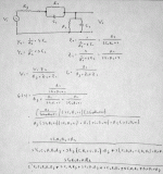
If you work out the xfer function (attached) for this, you have essentially a LPF.
The G(s) xfer function shows that there are two zeros: one at 1/C1R1 and one infinite zero.
There are two main poles, and two parasitic poles that come from the driver Zo. These parasitics can be pushed out of the passband by making them smaller than the other components that provide the desired poles.
We see that that is indeed the case since 39K||100K << R1R2.
The desired poles are located at:
w1= 1/C1R1
w2= 1/C2R2
The critical frequency:
wc= (C1C2R1R2)^-0.5
That should get you pretty close, but with networks like this, I'd prefer to drive it from a cathode or source follower to get that Zo down to reduce the problem of parasitic poles.
The A Number One problem with this design is the redundancy. You can't implement a second order network with resistors and capacitors. You need either an RLC network, or you need an op-amp or other active device to "fake it". Here, you have a pole falling right on top of a zero, negating each other, and the whole thing reduces to a first order RC filter.
C1 would seem to be included as a tweak or minor tone compensation of some sort.
Attachments
 Moving to Instruments and Amps.. See below:
Tubes / Valves All about our sweet vacuum tubes 🙂 Threads about Musical Instrument Amps of all kinds should be in the Instruments & Amps forum
- Status
- Not open for further replies.
