I've tried to make a ray digram with a non-point light source. Does this make any sense? I've tried to make to scale, with an estimated lamp arc-length of 20 mm.
I used the RAYTRACE program from http://members.ozemail.com.au/~imesoft/ to make the ray diagrams in case anybody wondered.
An externally hosted image should be here but it was not working when we last tested it.
I used the RAYTRACE program from http://members.ozemail.com.au/~imesoft/ to make the ray diagrams in case anybody wondered.
Hello Lentroo, thats close to what happens but remember that the light source is three dimentional so you will get multiple focused points in front of the fresnels. There is also spherical and chromatic abberation that can effect things slightly.
DJ
DJ
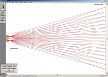
projection lens too far from LCD
In your ray trace, I think the projection lens is too far from the LCD. Your ray trace shows all rays diverging from the projection lens. That can only give you a virtual image. So you would have to look in through the projection lens to see the virtual image where the panel is. This is magnification, not image projection.
To make a real projected image, the rays leave the projection lens converging to a focal point, and then diverge to the screen. That is why the image appears upside-down.
The condensor system should focus the light at a point past the projection lens, not in front of it. Try using a second fresnel that has a focal length 10% longer than the distance from the LCD to the projection lens.
I think it also is misleading to include the condensor system and the projection system in the same ray trace. When you do, it looks like each point on the lCD is lighting only two points on the lens. In fact, every point on the LCD lights every point on the lens, but some lens areas get more light or less light depending on the direction(s) that rays are being sent by the condensor system. Adjust your lenses and try the tracing with just an edge point and a center point on the LCD.
I think this is where allot of people get confused with ray tracing, including myself, I'm still trying to get my thinking around it. There are two things I see happening in a projection, one is light intensity rays the other is image rays, although they are the same I like to separate them. The light intensity raytrace only shows where the light is travelling and is not directly responsible for the image projected. The image raytrace is only concerned with the light leaving the lcd and onto the screen. Although the light from the lamp does eventually get to the screen, I find it easier to separate the two. I'll give another example that might help. When a camera is used to capture an image onto a film, the light that the lens collects, starts as diffuse light and is reflected from the object into the lens, this is what I consider image rays. In a projector there is an extra process, where the light from a lamp is collimated and passed through the lcd. This is what I consider light intensity rays and to complicate things even more the light intensity rays don't just stop and the image takes over, the two are entwined and this is where uneven lighting shows up.
If anyone can understand what I'm babbling about and can explain it another way, please do, it's hard to write this in words.
I haven't seen this explained on the forums yet, maybe I missed it somewhere or I'm completely wrong.
DJ
If anyone can understand what I'm babbling about and can explain it another way, please do, it's hard to write this in words.
I haven't seen this explained on the forums yet, maybe I missed it somewhere or I'm completely wrong.
DJ
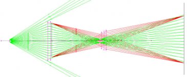
I think you've got it!
Very nice drawing. I think this is a much more accurate picture of what is happening in a projector.
BTW, most ray drawings just use the extreme rays and a central-axis ray to show you where an image will appear, or to show the light path. You can draw them by hand, using just a few simple rules about lens behavior. If you make them full-scale and accurate, then you can measure distances in the drawing to tell you how far apart to put lenses and LCD, etc.
Rule 1: A ray passing through the center of the lens is not bent.
Rule 2: A ray parallel to the central axis of the lens will be bent to pass through the focal point on the other side.
Rule 3: A ray passing through the focal point will be bent to be parallel to the central axis on the other side of the lens.
You can solve almost any lens problem by drawing a line using one rule, than adding a line using another rule. Where they intersect on the other side of the lens is your solution.
follow the rules!
Rule 3: A ray passing through the focal point will be bent to be parallel to the central axis on the other side of the lens.
If you put a point light source at the focal point of the lower fresnel, then rays on the other side of that lens would all be parallel to the central axis. But if you put that point light source to the left of the first focal point, then the rays on the other side will converge. If you put the point light source to the right of the focal point, then the rays on the other side will diverge.
In Lentroo's drawing, the light source is not a point, since he is trying to show what happens with a real lamp arc. So some light comes from above the focal point, and some comes from below the focal point. It is not explicitly mentioned in the rules I listed, but this can be derived from them: If the light comes from a point directly above the focal point, then those rays will all end up parallel on the other side of the lens, but not parallel to the central axis. Instead they will be parallel to the ray that goes through the center of the lens unbent.
If we had perfect point-source lamps, then each LCD pixel would only get light from a single direction. So the light from each pixel would only hit the projection lens at one point. Instead, each pixel is lit from all parts of the lamp arc, so the light from each pixel is spread out all over the projection lens surface. If the lens is perfect, then any such ray should be bent to light a single point on the screen. If the lens is not so good, or we try to use it beyond its angular limits, etc. then some of the rays don't end up at the same point on the screen. Then you get a low contrast image, or even a blurry image.
not the light-source, but the lens
That's very interesting Guy, I've been wondering a bit why the point light source should be so important. From what you're telling, the real problem is actually "imperfect" projection lens, and not the "wide" light source.
That would explain how the projection quality can be like night and day between different projection lenses.
It's both!
I think a large light source with a perfect lens would give a good resulting image. Or a point light source with even a poor lens would give a good result. The combination you want to avoid is a large light source with a poor lens. Then the different rays coming through an LCD pixel will not get focussed to the same point in the image.
But that was just in terms of image contrast and sharpness. You could also try to use a lens with too much magnification, and get a perfectly clear image but with all of the edges rounded like a fish-eye lens.
Would a non-point light source like a long-arc 2000 watt metal-halide fed into a lens to focus the light to a point, fed into a condensor fed into the fresnel/LCD allow one to use a larger long-arc MH versus the way more expensive short arc MH/HMI lamps?
I'm working on building a very high output projector... assuming I can move the heat absorbed by the LCD panel. Going to start by playing with an overhead, then move to a box w/ a MSR-400 bulb + ballast (from a club light). Once that is working, then shoot for really crazy lamps (MSR-1200 and HMI 2500 were the two I found that should have a short enough arc).
TIA.
shrinking the effective light source
You can concentrate a parallel beam using a positive lens to converge it, and then a matching negative lens to turn that cone back into a narrower parallel beam. Each air to glass transition losses some light, but a much narrower output beam would be much brighter. The focal lengths would need to be related by the change in the beam diamter. For example, a 100 mm wide parallel beam going through a positive lens with focal length of 200 mm, would converge 100 mm over 200 mm. If a negative 20 mm focal length lens intersected the converging beam at the point it was 10 mm wide, then it the light would come out as a 10 mm wide parallel beam. And that beam would be around 81 times brighter (assuming 10% loss in each lens).
I think you could do this, and the result would be a better image. But the problem with bigger bulbs is that the shape of the arc is very far from the 4:3 or 16:9 shape of an LCD. The reflector & condensor system captures as much light as possible, and then magnifies it so the image of some part of the arc fills the whole LCD. If you magnify a long arc to the point that the width of the arc covers the height of the LCD, then the light coming from both ends of the arc will fall past the LCD sides.
There is a way around this: You could use a pair of cylindrical lenses (they only refract in one dimension) to make a beam smaller (or larger) in one dimension, without affecting the other. You will probably have to design a pretty good condensor to get the beam down to a reasonable size before you filter out the heat with cold or hot mirrors. Then some combination of cylindrical lenses to make it into the right shape, and a normal lens to spread it into the cone of a standard lower fresnel.
Rolyn sells both positive and negative cylindrical lenses, but they are pretty expensive. You could do the same thing with cylindrical reflectors that you make yourself, if you are good with metalwork. It is much easier to make a one dimensional curved reflector than it is to make a two-D reflector.
- Status
- Not open for further replies.
- Home
- General Interest
- Everything Else
- The Moving Image
- Lighting and OHP
- Ray diagram with non-point light source