This is a power amp I have in mind , plz do not laugh yes I work things out brute force with my scope and breadboard , I am not a sim guy .
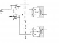
Here is the design I have in mind , input will be a sine wave about 2 V p-p anywhere from 300 hz to 20 khz . I am using op amps as phase splitters to drive the mosfets . This is what I believe to be a class A transformer coupled push-pull modified by me .
Mosfet will probably be a class-d lateral mosfet with 900 pf input capacitance and 12 , still choosing . Op amp is the lm8261 , wich is just perfect for my application from the looks of it .
So I am gonna be running 2 x mosfets per amp , so 1800 pf input , yes Its strange i know .
Transformer secondary is floating , load might be anything from capacitive to inductive , put an x value , I am not aiming for maximum power in 8 ohms or w/e , this can go from a couple mA to large amps , most likely a slightly reactive load load ... I wont go beyond 6 amps on the secondary side .
Transformer will be either 1:1 or 1:2 step up audio range type .
Plz tell me if this is good , is the biasing resistors good like this ? Do I understand things correctly ?
Attachments
How can I make this same design run in pure class A , isnt the resistor biasing making this class A
larryB;
Look at your design again.
With 0 Volts at the input your Opamps will try to set their outputs at 0 Volt.
Result: The Opamps will just draw Current through the resistors connected to +15 Volts until output is 0 Volt (as on the input).
You need to add a biasing circuit between the Opamp outputs and the output Fets......
- Status
- Not open for further replies.