Perfect! Thanks Mark - The California offers sounds great! One day maybe!
Will let you know how I get on with providing the Amanero its own supply. I also found another ribbon in my spares box for I2s but I'm not sure the DAC 9 board has many grounds to connect to. I can see that the Amanero does.
I can certainly try to make the I2S connection shorter
S
Will let you know how I get on with providing the Amanero its own supply. I also found another ribbon in my spares box for I2s but I'm not sure the DAC 9 board has many grounds to connect to. I can see that the Amanero does.
I can certainly try to make the I2S connection shorter
S
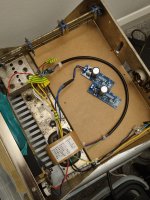
With flat ribbon cable do not cut the ground wires between the signal wires at the source (Amanero) as in your first picture but solder them to a ground pin at your DAC board. If your DAC board has only a single ground connection for I2S, use that for all I2S ground wires.
Amanero pinout:

As can be seen each of the I2S signal has a ground in the adjacent row. A 6-pin IDC and 6-pin ribbon should be able to plug right in. MCLK is a little trickier since the closest dedicated ground might be two pins away, at pin-8, or else share pin-15 ground with FSCLK (LRCK). Another possibility might be to connect pin-16 to ground on the board, then an 8-pin IDC ribbon could work? Otherwise a cable could be fabricated for MCLK I suppose. Problem with soldering ribbon cable intended for use with IDC connectors is that the wire without its insulation tends to be delicate and can fatigue crack pretty quickly if not handled carefully and infrequently.
As can be seen each of the I2S signal has a ground in the adjacent row. A 6-pin IDC and 6-pin ribbon should be able to plug right in. MCLK is a little trickier since the closest dedicated ground might be two pins away, at pin-8, or else share pin-15 ground with FSCLK (LRCK). Another possibility might be to connect pin-16 to ground on the board, then an 8-pin IDC ribbon could work? Otherwise a cable could be fabricated for MCLK I suppose. Problem with soldering ribbon cable intended for use with IDC connectors is that the wire without its insulation tends to be delicate and can fatigue crack pretty quickly if not handled carefully and infrequently.
Last edited:
Thanks for all the feedback and guidance. Have purchased the JLSounds i2soverusb, will take advice on wiring and come back here with results when the unit arrives.
I will use two TPs7A4700 modules to provide 5V for clocks and USB seperatley
bw
Stuart
I will use two TPs7A4700 modules to provide 5V for clocks and USB seperatley
bw
Stuart
Thanks to all as usual for sound advice! The JLSounds board arrived and they were very nice to deal with. A very small white strip was in the package which turned out to be 0805 resistors. Jeez.. these things are small! Getting old and eyesight not what it was but I managed to solder the 0805 across the B1 connection on the i2soverusb board! I then took the advice i received on here and made a better attempt at the i2s wiring. Used a ribbon and ran all the grounds parallel until i reached the Dac and then needed to find a common ground very close to the AKM chip data inputs. The guys at JLSounds also sent some OP1655's to try swapping for the NE5344's in the output stage. Well, I've never done opamp 'rolling' before and I didn't really believe in it due to so many mixed reviews but now I know! Very different sound to my DAC. (This was before the i2soverusb board btw). Anyway - much clearer top end but not my taste. I have decided to stick to the NE5344. Whenever I hear the top end clean up so dramaticlly i always feel it at the expense of the bass!! A simpletons view maybe! But - i realise that you CAN make alot of difference to sound by rolling opamps. I wonder if this could be that the circuit is not designed specifically for the change in opamp and maybe if both opamps circuits were setup correctly then maybe you would not notice such a difference? A mystery to me!
I have a new question - I wish to provide dedicated 5V to the i2soverusb board, not just for the clocks but also for the USB.
However, my toroid only has 9Vac windings and i'm feeding 2 regulator boards based on the TPS7A7400 LDO chip. This gives me 15Vdc rectified before it does the dropping to 5Vdc. According to JLSounds it will pull 100ma and 400ma on each section.
Do I just try this and see what the heat is like? Or do I need to buy another transformer dedicated to the JLSounds board. My head tells me that I may be able to split the voltage somehow so there is not such a drop but my electronics knowledge is not great. I do have some big resistors but I read this is not ideal because if the current changes then the voltage will change (know a little bit of OHMs law)....
AND - I'm using the TPS7A7400 just because i have them and they were not cheap! I have 3 of them and would love some advice on best use. I keep thinking I should also be working to improve the Vref quality feeding the NE55344's of the output stage.
So another option may be only use one TPS7A7400 board to power the clocks on the i2soverusb board (100ma and maybe more manageable across a 10v drop) and then build a simple linear supply for the USB section which requires 400ma. I have plenty of 7805's and caps and resistors lying about too!
Stuart

OPA1656 (the dual version) have been described at times as sounding a little thin in the bass. Nothing new there. Don't know that it has anything to do with frequency response either....some OPA1655's to try swapping for the NE5344's in the output stage.
Then you would need two power supplies and two transformer windings, one for each power supply. Otherwise you will defeat the galvanic isolation feature of the I2SoverUSB board. Better to use one power supply and one transformer winding for the clean side (and let USB power the dirty side), if that's what you can reasonably do. It should be fine that way....a new question - I wish to provide dedicated 5V to the i2soverusb board, not just for the clocks but also for the USB.
I2SoverUSB has internal regulators that will drop the 5v you provide down to 3.3v. Therefore the voltage regulator you use does not have to be unusually good. An LM317 or LM7805 could work fine....using the TPS7A7400 just because i have them...
You will need very clean power for Vref of the dac chip. That's more important than even the clocks. Clean power for the clocks matters too, but you also need clean power for the output stage. For DACs to perform at their best, they need various clean and isolated power supplies and voltage regulators. If on a budget then probably just try to put your best sounding regulators where they will do the most good. Clocks and the digital dac chip power pins need clean low noise power, but it doesn't have to sound good in the same way can matter for Vref (IME, its just a very sensitive load in terms of how it is powered). TPS7A7400 may not be the lowest noise, but you may still find it sounds better than some other regulators for Vref. You could try it and see what you think anyway.So another option may be only use one TPS7A7400 board to power the clocks...
Last edited:
OPA1656 is one of the better things in audio really closely followed by OPA1642. Opamps have developed to be parts that are the least of our worries today (as long as one decouples them properly).
Last edited:
Thanks again guys for your help. Ive left the LDO in providing 4.3V. I am very pleased with the sound. it is anoying that the jlsounds board now needs resetting in Volumio every time I power of the DAC unit. Possible no way round this.
Also, I may be entering the domain of insanity but i have shorted the outputs from the NE5344 with 2 x 10kohm resistors to make a mono output for the sub. Is this optimal? I'm sure the dac sounded better before I did this final mod!! It now sounds like ive lost a little clarity in the top end. Will probably remove the resistors and provide a more robust listening test
Also, I may be entering the domain of insanity but i have shorted the outputs from the NE5344 with 2 x 10kohm resistors to make a mono output for the sub. Is this optimal? I'm sure the dac sounded better before I did this final mod!! It now sounds like ive lost a little clarity in the top end. Will probably remove the resistors and provide a more robust listening test
Attachments

- Home
- Source & Line
- Digital Line Level
- Raspberry Pi and AK4399 and Amanero