It is a DF of the electrical triode system as element in global system inclouding final electrical load.Damping Factor is Rl / rp.
OT is not only the ratio transfrmer of units, but elemenet with loses. For final and more accurate DF.
More factors should be considered.
As:
FeddBack amount, Ri, RL, Rprim-dc, Rsec-dc, transformer Copper losses, Transformer Iron losses, Total losses and complex imedance of load.
.
In praxis we have more DF points between the active stages. So the care should be taken 1st to that. Every stage has own predecessor source as driver.
And if it is not considered it leading into over loading the tube as sources with higher equivalent impedances. Creating compression-limiter effect in audible outcome...
.
For instance if we have an amplification tube stage, what input source can be for not to cut off the highs, what the maximal load can be for not to have say -0.25db in the whole BW, in the same time in what value that load will decrease the load line...
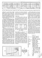
Dyna, before there was a Kit. From memory Dyna was a small company run by David Hafler & Walter Keroes building transformers & chokes. And like many other companies looking for a way to increase their business. Keroes was technical & thought there might be a way to sell a lot more iron cored products if they were building amplifiers using a rather forgotten circuit out of the 1930s.
Keroes bread boarded a trial circuit & found it worked rather well without any obvious problems. He liked how the internal resistance of the output to the speaker was being lower quite a bit, the contraption looked a lot like a triode amplifier. Distortion numbers were good compared to straight pentode, especially while driving a complex load like a loudspeaker.
So away they went, Keroes put together a technical article that managed to get published in Audio Engineering & other technical journals. Dyna was on their way, they called their amplifier Ultra Linear.
You, the reader, may do your own research to fill out & correct errors & omissions in my short Tome.
Attachments

Tube amplifiers that employ an output transformer:
Small Signal Damping Factor
I measure small signal output voltage, first with open circuit output, and then a non-inductive load resistor.
From that, I calculate small signal output impedance.
Then small signal Damping Factor = Load resistor Ohms / output impedance. (damping factor Referred to the load in Ohms).
Why only do a small signal damping factor?
In most cases, the real Damping Factor will never be better than the small signal damping factor.
The extra factors of large signals are output stage's plate variable rp impedances for SE tubes; and push pull AB with one tube cut off; and negative feedback, if employed, which only corrects as best it can for those extra factors.
The small signal test @ 1kHz, tells me the best that Damping Factor can be.
This works for most all kinds of vacuum tube output stages, and includes:
Things that effect Damping Factors
Tube plate impedance and/or effective plate impedance caused by negative feedback which does reduce effective plate impedance (Global, Schade, Cathode, and any other negative feedback that affects the output stage rp(s).
No Negative feedback
Negative feedback
Single Ended
Push Pull
Output transformer's secondary inductance in series with secondary DCR.
And . . .
Insertion loss of the output transformer @ 1kHz (There is almost always more insertion loss at 20Hz, and at 20kHz, than there is at 1kHz). The larger insertion losses at 20Hz and at 20kHz, almost always only make the Damping Factor worse than at 1kHz.
For those who are into OTL (Output Transformer Less), you can do your own predictive analysis of Damping Factor,
Or . . . just go and measure the output impedance, then refer it to a load impedance.
OTL Damping Factor even at small signal is sometimes Non-symmetrical, but is especially Non-symmetrical for large signals.
A simulation is a simulation, that is all.
A measurement is either good, not good, or just mediocre "nearly not, nearly so" (Thanks to the former King of Siam, and to Mr. Hammerstein).
$0.03
adjusted for inflation
Last edited:
I Estimate damping factors.
Then I Measure output impedance, and calculate Damping Factor from the measurement results.
Then I compare my Estimated DF, versus my DF from the measurement and calculation.
That lets me know if the Estimation was out in Left Field (did the Left Fielder drop the fly ball?)
Then, the thread discussion begins.
$0.03
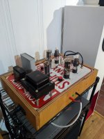
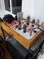
It has been some time since I built this amp. Burned it in in my garage and it is now in my living room. I mostly stuck to the original design, but I did drop the value of the screen resistor. The bottom line??? This is an astonishingly good amp. In fact, the best I have ever built. It is extraordinarily musical. Even my wife likes it. Actually she likes it a lot, so WAF for the large layout I chose is not a problem. The surprising part is that it is getting better as it ages in. I am using early Shuguang 2A3 tubes bought a long time ago in Hong Kong whilst I look around to others to try and nos 6C6s. The transformers at are Japanese OPT-5S 3.5k. I have attached a couple of pics.
My next project is to build a small 13FM7 compactron transformer input push pull design with the lowest part count I can manage.
Thanks for all the feedback!
My next project is to build a small 13FM7 compactron transformer input push pull design with the lowest part count I can manage.
Thanks for all the feedback!
Attachments
How good that looks!
Do you have any measurements of how the amplifier behaves?
voltages, Zout and thd etc??
maybe also some video of what it sounds like? I know it doesn't say much, but I like to see them play.
I have all the components to make it my winter project, when I finish it I will upload some photos too.
What type of speakers are you making it work with?
Thank you very much for all the information!
mrpunkk: I haven't made any measurements, maybe later in the year. I have thd measurement equipment so I will report back, but now I am simply enjoying it. The amp is in my living room driving a pair of half Chili Chang transmission line cabinets with GRS8 drivers and Linaeum tweeters. Earlier I had it driving a pair of B&C 12CXTs in small bass reflex cabinets. That also sounded great, but they live in my garage now being driven by a 2E22 se amp I also built. I strongly urge you to do this project, I am very happy with mine. (I like very simple things!)
What sort of output transformers are you using? Are they "under the hood/below decks", so to speak?
They are Japanese OPT-5S 3.5k. they show up on eBay when they have stock.

Hey, I finally finished building my 2A3 Radiotron, but I have a few questions.
1. Regarding voltage, the voltage reaching the tubes is roughly as indicated, but with the tubes installed, it drops to 100V on the 2A3 and half that on the 6C6. Maybe it's the power consumption, I don't know. The 2:1 ratio on the 6C6 remains the same. The 2.4V on the cathode of the 6C6 is at 1.2V.
2. The 45V on the cathode/filament of the 2A3 is 1.2V, not 45V, attached photo
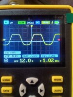
3.and with signal, 1v 1khz, it gives me 19v rms, it is a correct value for the 2A3/6c6, attached photo
4. Should I leave the negative (speakers) of the output transformers isolated from the ground of the general circuit?


1. Regarding voltage, the voltage reaching the tubes is roughly as indicated, but with the tubes installed, it drops to 100V on the 2A3 and half that on the 6C6. Maybe it's the power consumption, I don't know. The 2:1 ratio on the 6C6 remains the same. The 2.4V on the cathode of the 6C6 is at 1.2V.
2. The 45V on the cathode/filament of the 2A3 is 1.2V, not 45V, attached photo
3.and with signal, 1v 1khz, it gives me 19v rms, it is a correct value for the 2A3/6c6, attached photo
4. Should I leave the negative (speakers) of the output transformers isolated from the ground of the general circuit?
This photo shows when the output transformer (-) is grounded
why?That sounds to me like one leg of the 2A3 filament supply is shorted to ground.
Attachments
I didn't make any SE amplifier with 2a3 but I purchased a pair of 6S4S and I designed with these tubes a galvanically coupled amplifier in which I noticed that the best sound was when the limitation of the two alternations is symmetrical. Initially I tried a few static operating points and changed Zp until this symmetry resulted before clipping
why?
Keep in mind I'm certainly no tube amp troubleshooting expert, just applying some circuit network analysis to the voltages you showed and taking a guess.
You have a lot of voltage drop, especially a lot of voltage drop across the output transformer, which makes me think your 2A3 is drawing way more current than it should be. Since the voltage across the 750 ohm cathode resistor is only ~1.2 volts, it looks like that current is going somewhere other than through your cathode resistor, hence my suspicion of a short to ground in the filament circuit somewhere.
If the voltage measurements you posted are correct, there's something seriously wrong with the amplifier, as Charles G notes. The cause of the enormous voltage loss needs to be addressed before you do anything else. It cerainly seems like the cathode circuit on the 2A3 is shorted to ground. What power supply are you using?
I'm using a transformer made in my country by a reputable technician, 2.5v with a midpoint, maybe if I don't connect the midpoint on the grown bus?
It measures 2.5v between the 2 outputs of the transformer, and on the pot
It measures 2.5v between the 2 outputs of the transformer, and on the pot
The center tap of the 2.5 V transformer should be attached to the cathode resistor and cathode bypass cap, absolutely NOT to ground!
- Home
- Amplifiers
- Tubes / Valves
- Radiotron 2A3 values?