WRT ESR and Xc calcs, not that I'm aware of. I just use the same old formula as everyone else.Is cap ESR ever part of the Cx or the C...impedance, for resonant frequency or poles calculations? I've just never heard of it. But that's just me.. Hanze, I think in this case you're the pioneer. If you're just looking for the right sized cap to go with the choke load for best LF filtering, I will defer to the prior formulas and wish you find the best fit for your objective. I believe the math will out. Good luck with the project. Go Sixers!
Richard is definitely the pioneer here.. I can just see what it has to offer for my builds.. Math is fine for LF, its the other issue/s that I'm more concerned with. Cheers.
North Carolina Sixers.. had to google that one.. was thinking you were meaning the Sydney cricket team for a while there.
Classical approach is to reduce actual circuit to equivalent circuit.
For a constant signal level, could remove constant current supply, and replace the filter cap as a voltage source in series with a resistor, as a model for when average power consumption doesn't change. You could then simulate or experimentally measure the change in output signal distortion with change in capacitor ESR. I think that is the outcome you are trying to get some insight on.
For a varying signal level, and assuming your constant current source stayed constant, and assuming the signal stepped between a low and a high level, then that could be modelled by an added voltage source that has a constant dV/dt ramp between 2 voltage levels - assuming the average current drawn for the two signal levels are different due to typical class A operation. The added voltage source may not be large for a triode operating class A, but is noticeable for a pentode or pentode strapped as triode in a PP output stage.
Thanks trobbins, I'll need some time to think about what you write, straight off the bat it's a bit over my head. I appreciate the time you've taken.
Classical approach is to reduce actual circuit to equivalent circuit.
For a constant signal level, could remove constant current supply, and replace the filter cap as a voltage source in series with a resistor, as a model for when average power consumption doesn't change. You could then simulate or experimentally measure the change in output signal distortion with change in capacitor ESR. I think that is the outcome you are trying to get some insight on.
Mods please combine with post #25 at will.
trobbins when you say ESR, are you meaning Xc?.. I don't think so, but I'm unsure.
If the model used is to replace the cap with a voltage source and series resistance, then a simple variation is to change the value of that series resistance. As a model, that doesn't quite equate to a capacitor's reactive impedance and series resistance, and how that would affect circuit operation. Changing the model's voltage source series resistance is equivalent to changing the capacitor's ESR, and although it's not the same as a change in capacitor's reactive impedance, it may provide some insight.
North Carolina Sixers.. had to google that one.. was thinking you were meaning the Sydney cricket team for a while there.
Of course Sydney 6ers. I'm trying to get excited about T-20. We got some TV coverage of BBL up here for 2 seasons but not this year. I picked the Sixers to cheer for this year because they're 6 ers. I already have a NC Hurricanes team up here to cheer for so Hobart is out.
Of course Sydney 6ers. I'm trying to get excited about T-20. We got some TV coverage of BBL up here for 2 seasons but not this year. I picked the Sixers to cheer for this year because they're 6 ers. I already have a NC Hurricanes team up here to cheer for so Hobart is out.
If I can string a few days off I like the international test series, depending on venue, seats and weather it can be really good. Australia vs Sri Lanka at the moment. World cup semi final came to my home town two years ago, weather was good, seats were great, really enjoyable.
BBL/ T20 I see the appeal and have enjoyed it also. Live at the game its a bit kitch (four or six runs and they go nuts on the PA system with crazy music), but still enjoyable, and its a good night out especially if you're with kids. I would really like to attend one of the many sports that you guys cherish in the US sometime, baseball or NFL etc.. I've limited understanding but I think it would work out just fine (a bit like my capacitor issue, once I figure out what I need to figure out
") )
)
Last edited:
Unwanted coupling would come if someone attempted to use a supply rail like this to feed more than one stage. In that sense it is not a proper supply rail at all, but just local decoupling.
I don't understand the modern obsession with CCS. They have a role to play in electronics, but it is daft to sprinkle them everywhere as some seem to do.
I don't understand the modern obsession with CCS. They have a role to play in electronics, but it is daft to sprinkle them everywhere as some seem to do.
Unwanted coupling would come if someone attempted to use a supply rail like this to feed more than one stage. In that sense it is not a proper supply rail at all, but just local decoupling.
I don't understand the modern obsession with CCS. They have a role to play in electronics, but it is daft to sprinkle them everywhere as some seem to do.
Thanks DF96 re the unwanted coupling explanation. Seems I'm good to go if I keep the cap value at 20uF or so, I think to understand your comment re CCS, or at least the sentiment behind it, yet the CCS in my designs allow for functionality which otherwise would not be possible, and I'm happy about that.
Cheers.
Last edited:
 Please do NOT quote the entire post directly above yours when replying.
They're intended to be a single stage solution. This particular topology is one I have used in SE amplifier driver stages with ITs, and local cap decoupling, it prevents large variations in plate current with tube changes with very high transconductance triodes/triode connected pentodes I typically use in my driver stages. It also works well to isolate the supply from the driver stage - and is actually much cheaper to implement than multiple pi-filters to get the ripple down. The Achilles heal of the approach is both the size and quality of that decoupling capacitor to assure that the supply looks like a voltage source at audio frequencies.
When I don't use IT coupling I typically go with a hybrid driver circuit using a cascode CCS/follower with high transconductance triodes/triode connected pentodes. This gives me a gain = mu, low output impedance and lots of linear swing which is why I do it.
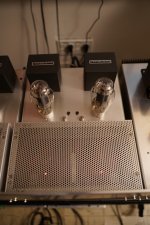
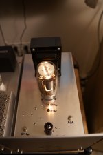
The GM70 amplifier (picture attached) uses the approach discussed. The 300B amps just use a hybrid driver based on D3A and cascode depletion mode mosfets. (It's just a glorified mu-follower.)
Practical uses for CCS shown..
When I don't use IT coupling I typically go with a hybrid driver circuit using a cascode CCS/follower with high transconductance triodes/triode connected pentodes. This gives me a gain = mu, low output impedance and lots of linear swing which is why I do it.
The GM70 amplifier (picture attached) uses the approach discussed. The 300B amps just use a hybrid driver based on D3A and cascode depletion mode mosfets. (It's just a glorified mu-follower.)
Practical uses for CCS shown..
Attachments
The Achilles heal of the approach is both the size and quality of that decoupling capacitor to assure that the supply looks like a voltage source at audio frequencies.
Kevin, could you please provide some insight as to what value of capacitor meets with your criteria as stated above?.. does it align more or less with Mr Sears calculations as per the link at the OP, or did you find the need to increase the value?. This would be very helpful information to me. Thank you.
Last edited:
I originally resonated the primary of the IT using a smaller capacitor value, I actually found it did not sound as good or work as well as I might have expected.. LOL This was to compensate (so I thought) for insufficient primary inductance, worked and measured exactly as predicted.
I would say the criteria used in the article would be the minimum and I would probably aim for around 1 - 2Hz typically as a target.
I still use this approach with ITs and high transconductance driver tubes in some designs and find it works well.
I would say the criteria used in the article would be the minimum and I would probably aim for around 1 - 2Hz typically as a target.
I still use this approach with ITs and high transconductance driver tubes in some designs and find it works well.
I would say the criteria used in the article would be the minimum and I would probably aim for around 1 - 2Hz typically as a target.
I still use this approach with ITs and high transconductance driver tubes in some designs and find it works well.
Thanks Kevin, that's exactly the info which I am looking for.
- Status
- This old topic is closed. If you want to reopen this topic, contact a moderator using the "Report Post" button.
- Home
- Amplifiers
- Tubes / Valves
- R. Sears - Minimising Power Supply Interaction