"Complete Wavelength TL?"
I'm currently playing around with a couple of rather ancient 12" x 6" elliptical drivers of unknown origin which (I was assured by my late father) are rated to thump all the way down to 20Hz. I was thinking of using them as bass units in an active set up with either one or four JX53's per channel.
Most of the TL designs that I've found are 1/4 wavelenghth, and seem to be quasi - bass reflex in their operation. I was wondering whether anyone had experimented with a full wavelength TL, and if so what were the findings? (I realise we're looking at forty-odd feet of internal accoustics here - don't tell the missus how big it'll be!).
Cheers,
Jezz
It won't work (as you want it to work)
For example your speaker F res. @ 30 Hz
Normal your tl would be about 2.5 meters long, you want to build one of 10 meters!!!
First of all the "resonant" frequency will be lower as where you want it to be:
For 2.5 meters 1/4 wavelength is 30 Hz
For 10 meters that’s 7.5 hz
The first harmonic is at 15Hz, the second is at 22.5Hz, 3rd is 30Hz
first of all it wil take a lot of energy to get the 30Hz to resonate (only because this is the 3rd harmonic) so your Q will probably be very high.
Your speaker will sound like more than a BR as ever before.
(My theory)
on the other side, for pulse response your speaker would act as an closed sub and thats always good 😀
Cheers for that Hilbren; one of the factors (not!) in the equation is, for example the F res of the chassis. I know it's a tall order, but I was trying to eradicate as many of the variables as possible.
Although I'm aware of Martin Kings TL formulae (http://www.quarter-wave.com/), it does rely on knowing a few(!) parameters of the driver in question. My idea (although undoubtedly impractical given the amount of required 180 degree turns in the circuit) minimises the effective internal volume whilst keeping the realisable colourisation above the operating frequency of the unit (eg width of line: 60cm = 500Hz/depth 1cm = 30KHz; length 10 x 100cm x 1cm = 1litre TL volume, far less than the required "infinate baffle" or sealed box volume required leaving more than a little room to play with). I'm hoping that (if any) the resultant 360 degree emissions will not cause blurring, whilst giving the driver a moderate internal pressure to work against. When operating at lower levels, I would expect the driver to realise more bass due to the lesser restriction on excursion as seen in some BR & IB enclosures, wheras higher levels might see a little augmentation from the TL port, effecting a more linear dynamic response. Since I'm frying my brain on this, I'd be really grateful for your take on the idea (disregarding the practical limitations of the 180 degree turns involved!)
Cheers, Jezza
An other factor (and this is a little offtpic) why is everybody always trying to push the bass output at lower frequencies with a principle that’s based on resonance?
BR or TL are both systems that only "amplifies" waveforms based on a sinus... so all the other details fall away... why???
BR or TL are both systems that only "amplifies" waveforms based on a sinus... so all the other details fall away... why???
Does your driver have any info/serial numbers on it? Could you post a pic? I have a suspicion it might be a Kef B139...🙂
Images of ancient ellipse...
Hi Pinkmouse,
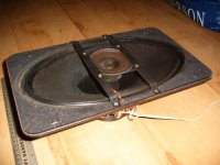
I think we'll be very lucky if it's a Kef - from what I recall, my father got them as end of run stock (more than thirty years ago) the original shipment bound for an upmarket "radiogram" or something of the like. It's certainly unusual, having a coaxial tweeter strapped across the front (removable via nuts & bolts thank Christ!) and a square chassis (13 1/2" x 8"). Fixing centres are 6 3/4" x 10" (just the four), and the front of the chassis sports a cork gasket - it's obviously designed to fit behind the baffle.
Hi Pinkmouse,
I think we'll be very lucky if it's a Kef - from what I recall, my father got them as end of run stock (more than thirty years ago) the original shipment bound for an upmarket "radiogram" or something of the like. It's certainly unusual, having a coaxial tweeter strapped across the front (removable via nuts & bolts thank Christ!) and a square chassis (13 1/2" x 8"). Fixing centres are 6 3/4" x 10" (just the four), and the front of the chassis sports a cork gasket - it's obviously designed to fit behind the baffle.
Attachments
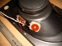
Although a little fuzzy, this image shows the unmarked coil; the "condenser" being hidden behind the riveted terminals. I've got a feeling it's a metal film capacitor - you can just see the red painted end but not much more, so the coaxial make-up was obviously a factory job rather than post production.
Attachments
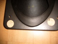
The only numbers on the back appear on two circular stickers about the size of a two pence coin (both having "MADE IN GT. BRITAIN" in standard print). One sticker has the numbers 92390 and DD15, the other 4272. My dad had fitted them with IB enclosures: 10" x 24 1/2" x 8" top & 13 1/2" bottom (slanted baffle) 10mm chip with a 10mm ply baffle. Allowing for the 10mm thickness I make that just a tad short of 36 litres.
Attachments
Although I can't find any evidence on the units, I know they're rated at 8 Ohms; my father fed them via the classic JLH Class A's at 27V; I've still got them & I'm scratching my chin as to whether or not I should keep them on duty for the bass section, whilst using a tube amp for the JX53's (comments welcolme!). So, if anyone can shed further light on the origins of these units I'd love to hear. For my part, I simply want to find a way to get the most from these elderly units without resorting to megawatts & equalisation.
Attachments

Mistery woofer
Hello everyone
Even though I can't pinpoint the origin of this woofer, one thing
is for sure, it's NOT a KEF woofer, a B139...
Being an old driver, made in Great Britain, I tend to think it will
be an ELAC driver, those woofers were sold a lot in GB in the 50
and 60 even though it was a german company. Excelent ones
by the way.
However I really can't swear about that.
But KEF B139 is not for sure, I still own 2 of those, they were saved from the rage of experimenting with diy amplifiers....
No matter how long you build the line, if it is open at one end it is a 1/4 wave resonantor... with a line a full wavelength of the Fs long, probably best to damp it until it is aperiodic (ie acoustic labyrinth), since open it should decrease the amount of bass possible.
It will also be BIG.
dave
It will also be BIG.
dave
Those drivers were made by (or for) EMI.
Very popular in their day, and used in a lot of domestic and pro gear. They did a few variations - plain cone, cone with whizzer, single tweeter on strap, twin tweeter on strap, and a specific bass version.
In the right cabs, the bass can be very good, but they're only suitable for high efficiency designs, as the highest rated version is only good for 20W, and the others considerably less.
If you come up with a good design, I'll be very interested - I have a few drivers sitting on the shelf ;-)
Jezz-the-Fezz said:My idea (although undoubtedly impractical given the amount of required 180 degree turns in the circuit) minimises the effective internal volume whilst keeping the realisable colourisation above the operating frequency of the unit (eg width of line: 60cm = 500Hz/depth 1cm = 30KHz; length 10 x 100cm x 1cm = 1litre TL volume,
Having some difficulty following your dimensions-especially the length listed as "10 x 100cm x 1cm = 1litre TL volume".
That seems to be 3 dimensions for the length, plus one liter volume for the enclosure which seems physically unrealizable for a 6 x 12 inch woofer.
Could you please explain?
Having some difficulty following your dimensions-especially the length listed as "10 x 100cm x 1cm = 1litre TL volume".
I didn't make it overly simple did I?

If you take a look at the word doc attached above you might be able to see where my weird logic springs from - note that it's not a design, just a means of playing with an idea.
If we assume that the sound velocity is 300M/S (which it won't be in this environment), the width of the chamber at 60cm equates to a potential resonance of 500Hz; not a problem if my x-over is <200Hz, the depth at 1cm equates to a potential resonance of 30,000Hz - again, unlikely to pose any difficulties as are any of the interim between the two.
You can see from the overly simplified make-up of the TL section that the overall length (broken up by 10 x 100cm sections) of the TL is ~ 10Metres, equating to a potential resonance of 30Hz. The volume of the TL section is 60,000 cubic centimetres (fudged my early morning maths previously!) so, 60 litres. (Not one!). No problem; if I shrink the width of the TL from 60 to 20 cm, I'm down to 20 litres, which still gives me 16 litres to play with in order to "funnel" the rear output of the driver into the TL section before I match the IB volume that my father employed. (phew🙄 ). I'm not surprised you couldn't follow!
Anything coming out of the port (i.e. 30Hz or more not taking the "funnel" volume into account which would still lower the cut off point) 30Hz being 360 degrees to the driver, should be in phase and thus addative
(too many losses in the TL section however, would mean that it wouldn't work in practice I'm sure!).
Jezz-the-Fezz said:
I've hatched a drawing to make my idea a little clearer.
The line in that design is too restricted, you need the line area to be 1/2 piston dia at the very least and idealy much higher (1.5-3x dia for dedicated bass lines) to get any gain out of it, may as well have a sealed or IB.
Your design would perform closer to a vented enclosure with a very long port than a TL.
You can see from the overly simplified make-up of the TL section that the overall length (broken up by 10 x 100cm sections) of the TL is ~ 10Metres, equating to a potential resonance of 30Hz.
Your resonances will be at the following frequencies using your simplified speed of sound approximation.
f1 = (1 x 300) / (4 x 10) = 7.5 Hz
f2 = (3 x 300) / (4 x 10) = 22.5 Hz
f3 = (5 x 300) / (4 x 10) = 37.5 Hz
and so on sticking with the odd number pattern. There will not be any even resonances, at those frequencies the open end output will be a minimum.
Based on the cross-sectional area of the line shown, I would not anticipate much bass contribution. The line is too long and to small in area. If your goal is to attenuate the rear wave so that the driver produces all of the output, and the box provides only absorption of the rear wave, I think have a good start at a workable design. In either case I recommend your measure the T/S parameters of your drivers and design the TL using computer modeling.
Can I take it (rule of thumb etc) that the Sd^2 is going to equate to that of a 9" circular driver?
According to this online claculator, the area of a 6" by 12" ellipse is approximately equal to that of a 8.5" driver.
For calculation purposes, the diameter of the cone, for speakers 8" and up, is usally 1.5" less than the diameter of the frame.
Basically, your Sd should be 37 square inches, by my calculations.
For calculation purposes, the diameter of the cone, for speakers 8" and up, is usally 1.5" less than the diameter of the frame.
Basically, your Sd should be 37 square inches, by my calculations.
- Status
- Not open for further replies.
- Home
- Loudspeakers
- Subwoofers
- "Complete Wavelength TL?"