Hi, there
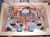
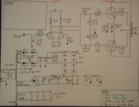
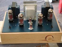
I just build my first tube amp (6l6GC PP 2 channel class A) I`m ready to test it, when I turn on the power switch everything goes correctly, filament circuit is ok, no problem. But when I turn on the beast with the standby switch, I saw glow red my power resistance (270 ohm 20 W) and a bit of smoke come out of it... so it`s too much for thoses resistance. Here`s some pics of the inside and the psu schematic.
Please tell me what should I do to make it run. Thank
Schematic : http://www.diyaudio.com/forums/showthread.php?s=&threadid=79628&perpage=10&pagenumber=5
(see post 44, the CCS I use is the one proposed by refference post 48-49)
Inside : see attachement
Thank a lot !
Attachments
Have you scheme for the amp to post here....?
Sounds like you have too much current flowing through 6L6 tubes...Assuming the Hot 270 Ohm, is the Cathode resistor.....
What voltage Negative do you have on the Grids of the 6L6 tubes....Again still assuming the 270 ohm cathode resistor is the 'Hot' one!
Sounds like you have too much current flowing through 6L6 tubes...Assuming the Hot 270 Ohm, is the Cathode resistor.....
What voltage Negative do you have on the Grids of the 6L6 tubes....Again still assuming the 270 ohm cathode resistor is the 'Hot' one!
Do they get hot without the 6L6 tubes fitted?
Are the 6L6 tubes Glowing anodes?
270 ohm does seem to be quite a high value resistor to have in the supply to the O/P stages......
Are the 6L6 tubes Glowing anodes?
270 ohm does seem to be quite a high value resistor to have in the supply to the O/P stages......
I think you've gone tooooo fast!
Beautiful wiring BTW. However, you should not be having basic
problems like this by the time the wiring is pretty and the lovely
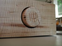
wood case is made. Lesson learned: You are a victim of your
own project management. 🙂
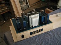
One thing I dont like are those 20W sand-cased resistors sitting on top of the bank of electrolytics. For one, electrolytics seriously lose life expectancy over 50C. By using them as heatsinks for the power R, you are just compounding a failure more. Second, those power R's need a much better thermal contact to wherever they are sending their heat... I'd get rid of them and get RH25 or RH50 rated aluminum bodied, finned power R's. www.handme.com has them. You will need two more M3 or #4 screws on your top plate to secure the power Rs. Further, apply a thin film of handy CPU heatsink grease to the bottom of the Power R to give it some nice thermal contact... The RH25's only cost about $5. They are a much better part than sand-encased speaker resistors.
Finally, if your resistors are cooking hot then you have a DEAD SHORT somewhere. Start measuring resistance to ground through your B+ path.. You're going to have to unsolder some of that lovely wiring to find the problem.
-- Jim
Beautiful wiring BTW. However, you should not be having basic
problems like this by the time the wiring is pretty and the lovely
wood case is made. Lesson learned: You are a victim of your
own project management. 🙂
One thing I dont like are those 20W sand-cased resistors sitting on top of the bank of electrolytics. For one, electrolytics seriously lose life expectancy over 50C. By using them as heatsinks for the power R, you are just compounding a failure more. Second, those power R's need a much better thermal contact to wherever they are sending their heat... I'd get rid of them and get RH25 or RH50 rated aluminum bodied, finned power R's. www.handme.com has them. You will need two more M3 or #4 screws on your top plate to secure the power Rs. Further, apply a thin film of handy CPU heatsink grease to the bottom of the Power R to give it some nice thermal contact... The RH25's only cost about $5. They are a much better part than sand-encased speaker resistors.
Finally, if your resistors are cooking hot then you have a DEAD SHORT somewhere. Start measuring resistance to ground through your B+ path.. You're going to have to unsolder some of that lovely wiring to find the problem.
-- Jim
Sounds like you have a short somewhere, normally a 20W 270 ohm resistor would not have a problem at the load currents we are talking about here. (say 100mA) Are your electrolytics wired backwards? Check for other potential miswiring.
Incidentally a nice set of chokes would provide more ripple rejection and better voltage regulation under load.
Incidentally a nice set of chokes would provide more ripple rejection and better voltage regulation under load.
Thank for your input, I'll check for short and miswiring tomorow, the power tranny is 270-0-270 @ 450 mA.. if it's help. For picture, you'll get some tomorow.
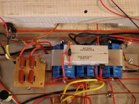
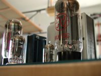
Hey, I might be wrong BUT, looking closely at the close up picture, The First cap is clearly hooked up backwards? At least To me it looks backwards, I see the point where the 2 -270ohm resistors are connected together and soldered to the NEG of the cap? The Black strip on the Rdial style cap appears to be neg.
That being the case, If you followed with the other cap polarities the same way , They could very wel all be backwards.
Trout
EDIT:
OOOPS bad viewing angle, I may be seeing a joint there I may not, Hard to tell
That being the case, If you followed with the other cap polarities the same way , They could very wel all be backwards.
Trout
EDIT:
OOOPS bad viewing angle, I may be seeing a joint there I may not, Hard to tell
The inputs caps are wired proprely, the neg side are all connected with the ground rail, I'll shoot more pic tomorow, right now I am working. 
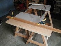

So this is my summer project,
and I want to make it sound good, so guys do you think its a short or only a lack of heatskin ? It take about 2 sec for the wire inside of the resistor to became red glowing hot.
and I want to make it sound good, so guys do you think its a short or only a lack of heatskin ? It take about 2 sec for the wire inside of the resistor to became red glowing hot.

- Status
- Not open for further replies.
- Home
- Amplifiers
- Tubes / Valves
- Quick urgent Help plz !