I am building a "Hybrid" subwoofer amplifier.
Each channel is a "push pull" configuration using the output boards shown here:
BPA300
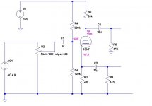
In the place of the "balanced driver board" I am using a 6SN7 "Split load Phase inverter" ala Williamson.
The inverter will only require 6mA @ 240V total. My power transformer for the chip amp is a very very large EI unit from a commercial DC power supply. It is approximately 35VCT @ 30 amps. I will be using splitting the secondary into two 18V secondaries and using 35 Amp Bridge rectifiers for the B+ and B- for the chips.(+/- 24VDC)
My question is this:
Rather than purchase a transformer specifically for the Tube HT supply can I just use a 120/12.6V transformer "backwards" off one of the large transformer windings? The transformer is 450mA 12.6VCT. If I cut off the CT and place it across one of the windings I get off load voltage of about 260-270VAC. I would then rectify with a bridge and CRCRC filter it.
My main concern is VA rating. I assume that 450mA @ 12.6V is 5.6VA. How do I calculate that in reverse?
Each channel is a "push pull" configuration using the output boards shown here:
BPA300
In the place of the "balanced driver board" I am using a 6SN7 "Split load Phase inverter" ala Williamson.
The inverter will only require 6mA @ 240V total. My power transformer for the chip amp is a very very large EI unit from a commercial DC power supply. It is approximately 35VCT @ 30 amps. I will be using splitting the secondary into two 18V secondaries and using 35 Amp Bridge rectifiers for the B+ and B- for the chips.(+/- 24VDC)
My question is this:
Rather than purchase a transformer specifically for the Tube HT supply can I just use a 120/12.6V transformer "backwards" off one of the large transformer windings? The transformer is 450mA 12.6VCT. If I cut off the CT and place it across one of the windings I get off load voltage of about 260-270VAC. I would then rectify with a bridge and CRCRC filter it.
My main concern is VA rating. I assume that 450mA @ 12.6V is 5.6VA. How do I calculate that in reverse?
If you only require 6mA @ 240V (which is about 1.5W) it will work. However, using such a small transformer, the regulation will probably be poor (=much voltage drop when tube draws more current). You can check this with a dummy load (be careful).
If it's too much of a problem you could just add some filter capacitance 🙂
Kenneth
If it's too much of a problem you could just add some filter capacitance 🙂
Kenneth
Last edited:
6ma X 240v = 1.44 W the same as 1.44VA but hooking that 12.6v transformer up to
that 18v winding should give you about 180vac not the 260-270v you mentioned if you are measuring an ac voltage that high it may be because of the verry poor load
regulation of small transformers. You might try loading the 120v side of the transformer with a load that will draw about 10ma I bet your loaded and unloaded
voltage will be way different.
I planned to use a decent amount of capacitance. The chip amp requires quite a bit of capacitance so I will have some big cans on top of the chassis. I can balance the look "aesthetically" with some big JJ caps.
I was looking for someone to tell me either I was "crazy" or it would work. Thanks.
I plan to start a thread about the project soon.
I wanted a LOT of power and tubes just get WAY TOO expensive when you near the 100 watt mark.
SS is not my favorite BUT I figured the Phase Splitter being a TUBE kind of makes up for it. I look at the Chip Amp boards as REALLY Powerful TRIODES.
The amps will be driving Alpine 12" Car Audio Subwoofers in Large Sealed Enclosures. I have had these woofers for years from back in my car audio (younger) years and they have never been used. I figure I might as well put them to use in my listening room. Since the sensitivity is pretty low (88db) I needed some "oomph" to keep up with the rest of the system.
A "group buy" came up on the boards so I looked over AlexW's design and saw the opportunity to throw in a tube and it just blossomed from there.
Attached is the splitter schematic. The 10uF caps and 47K resistor are at the input of the boards.
Attachments
Woody,
You are correct! I must have crossed up my notes between the bench and the computer. Now I have to re design the splitter to work with a lower B+ more like 180V.
No load voltage out of the "primaries" (now the secondaries) is 155V. So rectified and filtered will be below 200V.
THANKS!!
You are correct! I must have crossed up my notes between the bench and the computer. Now I have to re design the splitter to work with a lower B+ more like 180V.
No load voltage out of the "primaries" (now the secondaries) is 155V. So rectified and filtered will be below 200V.
THANKS!!
You can always put two transformers in series if you need more voltage 🙂 Decent trannies are insulation tested at at least 1kV so no worries.
By the way -- if it's just for subwoofer use it makes a lot of sense to go the hybrid route. Even tube partisans will see the sense in that 😉
By the way -- if it's just for subwoofer use it makes a lot of sense to go the hybrid route. Even tube partisans will see the sense in that 😉
- Status
- Not open for further replies.