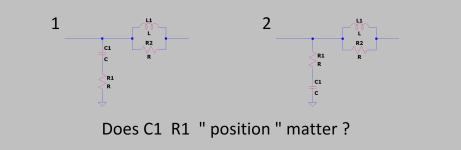

@JonSnell Electronic I have seen both variations used, that's why I wasn't sure if there is a difference or not. Thanks for the reply !.
Zobel network is used to compensate the inductive rise (with the frequency) of the speaker impedance
and to assure the amp stability. Since it is connected in parallel with the speaker, care must be taken
to properly dimension the power/AC current ratings for these R-C.
To answer your question the capacitor must be connected to the ground, because it has bigger size than R
and will work as antenna, collecting all the el-magn. or el-static interference, and has the smaller
impedance, keeping the node of R-C connection at a lower impedance to the grnd, shorting that interference
signal to the grnd and preventing it from getting into the FB input node.
And, following this rule, the outer layer of the cap "winding" must be connected to the grnd, shielding
the internals of the cap.
I fact, the same considerations need to be applied to the grounding leg of the Voltage NFB R-R-C network,
where the cap will be electrolytic.
Is that right? Most of amps we see these days have Miller compensation, and also Zobel network.If the amp is with Miller compensation. The RC is not necessary.
The RC is essentially a shunt compensation.
What does RC network at the output do for a modern amplifier? Nobody really knows nowadays. We just copy and paste the existing block from the old designs.Is that right? Most of amps we see these days have Miller compensation, and also Zobel network.
In the old day, the open loop gain of the amp often depends on the load. The more load on the output, the less the open loop voltage gain it has. You remove the load, the gain shoots to the moon, and it oscillates. That's why people put a RC network at the output make sure, at the high frequency, there is a load resistor presenting. BTW, if the RC is required, it should be as close as possible to the output stage, before the coil.
If the amp is miller compensated, it should be stable no matter there is load or not. Actually, the RC does more harm than the benefits. It puts an extra load at high frequency.
Last edited:
Meaning Cdom of the VAS and the filter in the NFB ?.miller compensated
Attachments
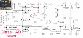
Only the 68pf is the Miller cap in your circuit.Meaning Cdom of the VAS and the filter in the NFB ?.
Even Self seems not to be able to explain precisely why the universally optimum values are 10 Ohms and 0.1uF for the Zobel network .
However, I can tell you from practical experience that you should always use a Zobel network.
It should run from the output node of the amp - so directly at the junction of the emitter degeneration resistors in a typical EF bipolar output stage to the main filter capacitor 0V junction.
Don't forget the out put inductor either - 2-5uH with 2.2 Ohm 3W resistor in parallel.
If you...
Hi @AllenB
The message your quoted is not all correct. I know most people will buy that idea.
I agree that you always should put an inductor to the output. You could parallel it with a resistor if you believe so. (I don't)
If the power supply is on a separated board, you should always add some bypass capacitors near the output transistors on the amp board. If there is a Zobel network, the ground should always be tied to the middle point of the local bypass capacitors. Not from the ground on the power supply board. BTW, your speaker ground should be tied from the same point.
I also use an RC network on the output of power amps. Even using a Miller capacitor, the opportunities for oscillation arise from the several phase shifts which are present, and modern high speed transistors extend that to high frequencies. Theoretically, of course an amplifier using Miller is stable, but at high frequencies forward feed in capaciances of devices can make it differ from a simple one step feedback network.
The concept is not so much whether it is 0.1 uF more a point of ensuring that the load is resistive, and as intended (hence the generally universal 10 ohms), rather than risking a higher gain with an unspecified load or open circuit. Capacitances in the range 22nF-100nF could be used.
The concept is not so much whether it is 0.1 uF more a point of ensuring that the load is resistive, and as intended (hence the generally universal 10 ohms), rather than risking a higher gain with an unspecified load or open circuit. Capacitances in the range 22nF-100nF could be used.
The correct value depends largely on the parasitics of the output transistors used, so manufacturers have converged on making devices where 10ohms is close to optimum because this results in the most usable BW in audio amplifiers since it is close to the intended load impedance. If for instance you used modern MOSFETs not optimized for audio, you might find the optimal zobel resistance becomes a funny value and the design becomes hard to optimize for 8ohms, or the P-channel parts want a dramatically different value than the N-channel parts. You can end up needing a high-power zobel resistor to make it work.
So yes, the 10ohm 100nF zobel is a weird copy paste artifact, but it is valid because whether deliberate or not, the market converged on an optimum balance of output transistor characteristics for 4-8ohm loads (possibly the semiconductor manufacturers received guidelines from those who understood the math). Note that although speakers are not exactly 8ohm resistors, 8ohm loads are what is used in engineering the amplifiers and generating final specifications, so they naturally gravitate to parts which give the best results with their test loads.
So yes, the 10ohm 100nF zobel is a weird copy paste artifact, but it is valid because whether deliberate or not, the market converged on an optimum balance of output transistor characteristics for 4-8ohm loads (possibly the semiconductor manufacturers received guidelines from those who understood the math). Note that although speakers are not exactly 8ohm resistors, 8ohm loads are what is used in engineering the amplifiers and generating final specifications, so they naturally gravitate to parts which give the best results with their test loads.
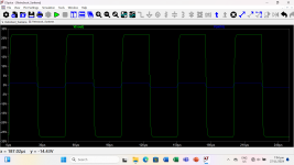
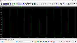
While working with my bootstrap amp to handle 6ohms load, a small spike appeared at the minus rail while injecting a 20KHz squarewave in simulation. It was surprising that what flatten it was lowering the value of 100nf to 47nf in the zobel network. I was using Sanken models for the outputs but when using the stronger Toshiba 2SC5200/SA1943 the spikes did not appear.
PS You may have to zoom-in the attached image to see the spike mentioned.
PS You may have to zoom-in the attached image to see the spike mentioned.
Attachments
I guess it would be better if you remove the capacitor entirely. Could you share the schematic?It was surprising that what flatten it was lowering the value of 100nf to 47nf in the zobel network.

The output transistors used in your schematic are to220 2A rated transistors. They are not capable to drive 4 Ohm over 8 Vpk.I may have to increase the tail currents to handle 6r load and use the Sanken outputs or remain as it
You are quite right! I must have downloaded a different datasheet I was under the impression that the Sanken model was a TO-3P device. So that explains why, I was using the wrong Sanken model for the outputs. Thanks for finding the error jxd!
- Home
- Amplifiers
- Solid State
- Quick question regarding zobel network