Off hand does anybody know what power transformer can drop into the PP-C1 without any schematic changes?
NO,
372X doesn't have the High Voltage current capablity you need or the heater supply current capability.
Look up the specs for a pair of triode connected EL34's (at Duncan Amp pages).
High Voltage Current is 130mA at zero signal and 142 mA at max signal.
Allow 8mA per side for the front end ECC88's (16mA total) and that means 148mA at idle and 158mA at full output
For heaters 2 x EL34 + 2 X ECC88 comes to 3.8 Amps
Use a 372FX
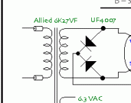
The High Voltage is 300-0-300 which means that the rectifier changes to a diode from each side to the output and the centre tap goes to ground instead of the bridge rectifier arrangement. Its rated for 150mA DC BUT because you are not using the 5V winding and not fully loading the 6.3V Heater winding it will handle that 158mA at full power easily. The slight reduction in high voltage resulting from 300 instead of 310 means that your amp will be 16 watts instead of 16.5 Watts - not worth obsessing about.
It has 5 Amp Heater capability so you are only loading that to about 75%.
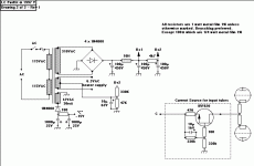
The -15V supply to where the front end diff amp returns does not have to be exactly -15V. You can get -12V by voltage doubling the unused 5V winding and that would suffice. You could use a second transformer if you wish to generate the -15V (especially since one of those tiny PCB Mount types would do - required VA is less than 1) but its not really necessary.
So all done with one tranny.
Cheers,
Ian
Edit: Thats 1 channel ONLY. You need a 372FX for EACH Channel
372X doesn't have the High Voltage current capablity you need or the heater supply current capability.
Look up the specs for a pair of triode connected EL34's (at Duncan Amp pages).
High Voltage Current is 130mA at zero signal and 142 mA at max signal.
Allow 8mA per side for the front end ECC88's (16mA total) and that means 148mA at idle and 158mA at full output
For heaters 2 x EL34 + 2 X ECC88 comes to 3.8 Amps
Use a 372FX
The High Voltage is 300-0-300 which means that the rectifier changes to a diode from each side to the output and the centre tap goes to ground instead of the bridge rectifier arrangement. Its rated for 150mA DC BUT because you are not using the 5V winding and not fully loading the 6.3V Heater winding it will handle that 158mA at full power easily. The slight reduction in high voltage resulting from 300 instead of 310 means that your amp will be 16 watts instead of 16.5 Watts - not worth obsessing about.
It has 5 Amp Heater capability so you are only loading that to about 75%.
The -15V supply to where the front end diff amp returns does not have to be exactly -15V. You can get -12V by voltage doubling the unused 5V winding and that would suffice. You could use a second transformer if you wish to generate the -15V (especially since one of those tiny PCB Mount types would do - required VA is less than 1) but its not really necessary.
So all done with one tranny.
Cheers,
Ian
Edit: Thats 1 channel ONLY. You need a 372FX for EACH Channel
Thanks for the assistance!
Thanks for the response. In the interest of full disclosure my next amp build is between this and the Baby Heuy 😉 and maybe the El-Cheapo, basically because I'm weak on tech skill but high in craft skill and thus I base most of my decisions on completeness of schematics, availability of parts, a general consensus by the DIY community of the projects quality, with the addition of a high challenge rating. This will be my second amp, the first went pretty well.
So on with the next question.
So instead of 4 of the 1n4008 you would only need 2 and the ground connection would come of the center tap and not where the 2 diodes come together?
hmmm I'm interested in this and will have to look up how this is done. If it’s terribly easy an explanation would be appreciated.
Thanks again, I've enjoyed reading about the Baby Heuy, what I've understood at least 😀
Pablo
Thanks for the response. In the interest of full disclosure my next amp build is between this and the Baby Heuy 😉 and maybe the El-Cheapo, basically because I'm weak on tech skill but high in craft skill and thus I base most of my decisions on completeness of schematics, availability of parts, a general consensus by the DIY community of the projects quality, with the addition of a high challenge rating. This will be my second amp, the first went pretty well.
So on with the next question.
The High Voltage is 300-0-300 which means that the rectifier changes to a diode from each side to the output and the centre tap goes to ground instead of the bridge rectifier arrangement.
So instead of 4 of the 1n4008 you would only need 2 and the ground connection would come of the center tap and not where the 2 diodes come together?
You can get -12V by voltage doubling the unused 5V winding and that would suffice.
hmmm I'm interested in this and will have to look up how this is done. If it’s terribly easy an explanation would be appreciated.
Thanks again, I've enjoyed reading about the Baby Heuy, what I've understood at least 😀
Pablo
Voltage doubler
Ok I found this on line. It stated that for a neg. polarity reverse the diodes. Would this arrangement work for doubleing the 5V and are the cap values important? Would the 1N4008 and 1000 uf caps in the original schematic be sufficient? Thanks again for the help, maybe this will all sink in someday 🙂
Ok I found this on line. It stated that for a neg. polarity reverse the diodes. Would this arrangement work for doubleing the 5V and are the cap values important? Would the 1N4008 and 1000 uf caps in the original schematic be sufficient? Thanks again for the help, maybe this will all sink in someday 🙂
Attachments
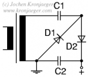
This is the more common simple voltage doubler :
both this and your suggested one are described here: http://www.play-hookey.com/ac_theory/ps_v_multipliers.html
SveinB.
An externally hosted image should be here but it was not working when we last tested it.
(reverse diodes for neg. supply)both this and your suggested one are described here: http://www.play-hookey.com/ac_theory/ps_v_multipliers.html
SveinB.
Yeah
I saw that one but I wasn't sure what to do with the two outputs, so I looked for one with just one output that could be + or -. Hehe if you need the one of the treaties of paris or the Russo-japanese war explained I'm your guy but its the simple things in electronics which stump me. Thanks for responding though, I'll have to figure it out.
I saw that one but I wasn't sure what to do with the two outputs, so I looked for one with just one output that could be + or -. Hehe if you need the one of the treaties of paris or the Russo-japanese war explained I'm your guy but its the simple things in electronics which stump me. Thanks for responding though, I'll have to figure it out.
Wait
On the you posted SveinB, can the bottom output, next to that ground connection just not exist and just use the top one? That was either really dumb or a breakthrough 😀
Second. Quote form the site
"Nevertheless, the output ripple of this circuit is significant, and will normally require either additional filtering or regulation to be usable by most electronic circuits"
Will this be an issue? Does the CCS provide filtering? I assume since it is a Constant Current Source that that the regulation is implied. Again that was either really dumb or a breakthrough 😀
Thanks for the help
Ok, ok
I'm trying to be proactive 😀 I downloaded PSUD2 and fiddled around with it. It suggested a cap values of 470uf, it had the 1n4007 diodes not the 1n4008. The voltage across the load resister was ~11v
I'm trying to be proactive 😀 I downloaded PSUD2 and fiddled around with it. It suggested a cap values of 470uf, it had the 1n4007 diodes not the 1n4008. The voltage across the load resister was ~11v
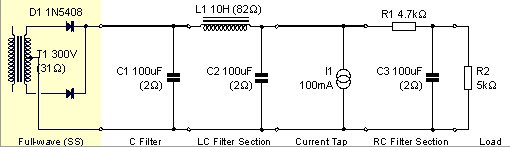
PSUD2 model
Does this look right? I'm not sure about all of the values; I just tried to get them close. I'm assuming the resister at the end is support to represent the load of the rest of the circuit? What are the B+1, B+2 suppose to be? Thanks for helping me work this out.
Does this look right? I'm not sure about all of the values; I just tried to get them close. I'm assuming the resister at the end is support to represent the load of the rest of the circuit? What are the B+1, B+2 suppose to be? Thanks for helping me work this out.
Attachments
The PSUD2 model above is a full-wave rectifier. Selelect Voltage Doubler instead (or simulate with half-vave for 1/2 of the voltage).
I suggest large first C for max voltage and minumum ripple. Use an additional RC filter if necessary to get the ripple down to a mV or so. To squeze the last volt out of the circuit use Shotkey diodes.
Svein.
I suggest large first C for max voltage and minumum ripple. Use an additional RC filter if necessary to get the ripple down to a mV or so. To squeze the last volt out of the circuit use Shotkey diodes.
Svein.
- Status
- Not open for further replies.
- Home
- Amplifiers
- Tubes / Valves
- Quick question on the PP-C1 amp