[SOLVED] Quick question about LED integration in circuit
Please excuse me if this is a very basic question, but electronics is not my strength, I am pretty much a total newbie.
I have built a raspberry pi based audio streamer with a linear voltage regulator (a kit), I integrated a power switch, and now would like to add an LED to the circuit that indicates whether the power is on or not.
My LED is this one:
https://www.digikey.bg/product-deta...td/103SYGD-S530-E2/103SYGD-S530-E2-ND/2691423
I would like to connect this LED to the output of the linear voltage regulator, which is 5V. Calculating this, I would need a 150 Ohms resistor. I got this far... but, my question is, does it matter whether the raspberry is on the same circuit? Would this change the calculation?
My thinking is to directly connect the LED to the positive and negative of the linear power supply output, with the resistor to the positive lead before the LED.
Am I on the right track, or am I missing something?
Last edited:
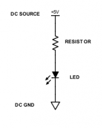
My thinking is to directly connect the LED to the positive and negative of the linear power supply output, with the resistor to the positive lead before the LED.
Yes, the LED and resistor should be connected in series, and across the 5V supply, with the LED cathode nearer the common (ground) terminal. If you use 150 ohms, the 20mA current will be near the maximum 25mA current rating, and the LED will be rather bright. You could instead use either a 620R for 5mA, or a 300R for 10mA.
Attachments
Last edited:
Thank you for your help. I will try out a couple of higher ohms resistors to see how much brightness I like.
You say the LED cathode should be "nearer the common (ground) terminal". I was planning to wire it; the wires will span 10 inches or so. Not sure if that is too far from ground? Why should the LED cathode near the ground?
You say the LED cathode should be "nearer the common (ground) terminal". I was planning to wire it; the wires will span 10 inches or so. Not sure if that is too far from ground? Why should the LED cathode near the ground?
We are talking *electrically* near ground.
Yes, we put it this way because the LED and resistor could be interchanged,
but as long as the LED cathode is "nearer the ground", it will still work the same.
Of course, your definition is fineYes, we put it this way because the LED and resistor could be interchanged,
but as long as the LED cathode is "nearer the ground", it will still work the same.
") , I was just clearing it up for the OP who seemed confused by it
, I was just clearing it up for the OP who seemed confused by it - Status
- This old topic is closed. If you want to reopen this topic, contact a moderator using the "Report Post" button.
- Home
- Source & Line
- PC Based
- Quick question about LED integration in circuit