Looking for a little guidance trying to resurrect an old pair of Dynaco A25s. These appear to be an intermediate model, ferrite 25F-EW woofer but with the 1.5” H087 tweeter, date on tweeter indicates 1976. These are beat to hell and been in storage for last 25 years, ridden hard and put away wet, but there’s enough there to save. I’d feel bad not trying. One speaker’s intact, other has a badly ripped cone and a dead tweeter. I patched up the cone pretty well, till I find replacement, and found and am waiting on an old H087 from eBay. Speakers belong to a cousin and come paired with a lovely Nikko TRM600 that’s in clean shape and I got running after a spell on a Dim Bulb Limiter and quite a bit of Deoxit.
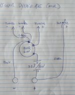
This A25 pair seems unique, for the XO there’s pot instead of the switch with the resistors. Pot is 50R Linear with a 2.5uF capacitor, pot is set up as a divider, if I understand correctly it’s an L-Pad and same as the more typical resistors and switch set up of 10R and 5X 2.2R. Both pots are completely trashed so I can’t get a reading off them to figure out what the series and parallel resisters would be for flat/normal which should be with the pot centred seeing it's linear. Speakers are all original, I’m the first person to ever crack them open.
I want to replace the pot and cap with a simple in series cap and resistor to give flat response. The cap seems a little weird as it’s very low at 2.5uF instead of the typical 5uF or even 8uF usually seen. Maybe this change was made to accommodate the then new ferrite woofer which from reading on the web had slightly different characteristics than the alnico. Right now I’m running them with 3.3uF / 10R I luckily had in my parts box. I used that combo as it’s what SEAS uses for their A26 kit but I really doubt their modern drivers are exactly like the old Dynacos, or my oddball Dynacos.
Early test sounds pretty good, these have a lot of bass though pretty one note, sounds like college 1978! Hard to judge with one tweeter still out, but tweeter seems a touch forward, bit detached, could be just a bit more integrated.
I need to order up the resistors, caps, and binding posts so any advice how to set these up for flat given the below drawing would be much appreciated. I figure best to set them up as they were originally designed and tweak from there if necessary. I’d prefer to ditch the L-Pad resistor combo for just a single resistor in line with the cap, unless that’s a bad idea. Much appreciate any guidance.
Attachments
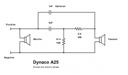
Here's a two resistor circuit for the standard A25, but your driver(s) are different.
Try with some junk resistors first, you'll likely have to iterate. Keep the 5uF though.
Try with some junk resistors first, you'll likely have to iterate. Keep the 5uF though.
Attachments
Last edited:
A simple pot wil cause the amp to see a higher impedance in the tweeter circuit.
Higher impedance, smaller cap.
If they have a mark for flat/normal, it is probably @8ohms. With the tweeter it looks like 16.
This is why an L-pad is nice. Doesn't move the crossover point.
Higher impedance, smaller cap.
If they have a mark for flat/normal, it is probably @8ohms. With the tweeter it looks like 16.
This is why an L-pad is nice. Doesn't move the crossover point.
A simple pot wil cause the amp to see a higher impedance in the tweeter circuit. Higher impedance, smaller cap
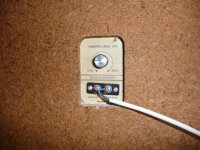
Wow, an even worse idea and cheap cop out than I thought. Good riddance to bad pots. I'm in Italy, maybe these were some economic versions for the southern EU market?
No indication for "Normal" and now I know why, be too odd looking to have "Normal" so off to one side.
Attachments
Try with some junk resistors first, you'll likely have to iterate. Keep the 5uF though.
Is it correct that I'd vary the series resistor (6.6R) first? I can already see varying both will make my head hurt 🙂
....I can already see varying both will make my head hurt 🙂
It's extremely difficult to make a good XO; manufacturers devote a lot of effort to tricky fine-tuning. If anybody ever gave it much thought, it would seem a really inept way to drive the two drivers and just plain silly notion albeit very convenient typology for manufacturers of an earlier generation.
But if you borrow a DSP, you can dial-in different settings to see what sounds and measures best. Then you eyeball what the DSP has been sending to the two drivers and then you duplicate those plots by buying pieces that cost almost as much as simply buying a Behringer DCX2496.
B.
Last edited:
Behringer DCX2496
Thanks for turning me on to that. What a cool thing for €200, I had no idea, Behringer does it again. I work in A/V so this could prove useful in the future, certainly to people I know - for €200 nice toy to have. For myself I don't plan on going beyond fixing these Dynacos, I build and play around with tube amps and guitar cabs on a sophomore level, but I leave hifi speakers to more knowledgeable people - and better carpenters.
I think I got the Dynaco tweaking idea, follow the old switched crossover combinations and hear what sounds best.
10R / 11R
12.2R / 8.8R
14.4R / 6.6R
16.2R / 4.4R
18.8 / 2.2R
Bit of a pain, I'd have buy up all the resistor combos and move the XO to the outside with some screw terminals, blah, I'll try rayma's combo first and hope that hits it. If I find a replacement 25F-EW woofer at a fair price I might then invest the time on it.
Question on the cap - better to go down to 4.7uF or up to 5.6uF? I know it's a small matter w/ a first order XO but I'm persnickety.
Oh, and rayma, that bypass cap is really 1uF not .1uF?
Attachments

- Home
- Loudspeakers
- Multi-Way
- Quick Dynaco A25 Crossover Advice Needed