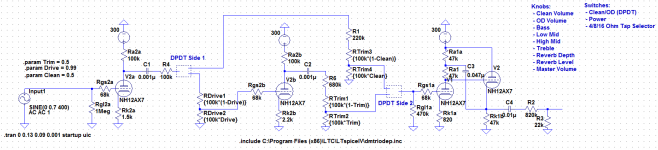
I'm working away slowly on an amp design in which I'd like to implement the Clean/OD channel by switching in an extra series gain stage for OD and bypassing it for clean. Please take a look at the attached picture to see a snip of the preamp portion I'm talking about.
Right now I'm putting half of a DPDT switch before the extra gain stage and the other half at the return point - an idea to isolate the channels at two points instead of one in case some of the signal jumps across the switch. I'm still not confident that will isolate properly, since the clean and OD channels have independent volume controls and I think the OD channel will pick up and amplify noise with the switches in this configuration, especially if the OD volume is high.
Would it be a better idea to use both halves of the DPDT at the send point instead, so that the channel not being used is grounded?
Attachments
it is common to ground the signal path of the gain channel in one or more places while the clean channel is in use, to prevent crosstalk. Of course not all do. You may not need to switch the input. Look at these examples:
Classic 30, adds in two triodes (V2) for gain channel, only switching output of stages. That sounds like the system you propose.
http://bmamps.com/Schematics/Peavey/Peavey_Classic_30_Schematic.pdf
6505+ combo, in this they switch only the outputs, but do ground the input to the gain channel with relay S4.
http://bmamps.com/Schematics/Peavey/Peavey_6505+_112_Combo_Schematic.pdf
The relay end of R4 (to the right on the drawing) needs a high value resistor to ground to prevent popping when switching channels. Or eliminate the relay. As the relay switches, there is a moment between poles where R4 would be unterminated, allowing a charge to start accumulating on C1. That can cause pops when that bit of charge gets shunted to ground by the circuits on either switch pole. I hope I articulated that well enough.
I don't know that any signal will "jump across the switch", but the high signal levels of the gain channel stages can radiate signal which can be picked up by the clean channel stages. So you would want to stamp out the activity of the gain stages while on clean, but i don;t think within the switch is the problem.
Hi Guys
Use shunt switching if you want it to be quiet.
Place one pole of the switch across Rdrive2.
Ground the wiper of the second switch pole and tie one end to the top of R6 and the other end to the top of Rtrim3.
In one position the signal to the second stage is shorted, so zero signal and its output is also muted - a note about this below. Meanwhile signal is allowed to pass through the clean attenuator. In the opposite position, the clean path is muted and signal goes through the second stage.
Note that muting the output of the second stage may not be necessary since there is only one stage in the gain path. If the output attenuator and the clean path attenuator form a mixer, then the second stage output can remain 'live' all the time.
An alternative to removing the second stage is to simply switch the amount of attenuation going into it and out of it for the two sounds. This keeps the signal phase the same for both sounds - if that matters to you - and again allows quiet shunt switching.
Have fun
- Status
- Not open for further replies.