In this thread I combine several questions I have regarding two designs, this to reduce the number of threads I start. Looking forward to your reactions!
1) Making a load line for 2xel34 in p-p class ab for a Marshall plexi I got the following result( picture 1). Notice how the load line enters the 25W max dissipation curve. I assume the max dissipation curve is for class A and I can average it for p-p.
Does this mean that I can effectively double the max dissipation curve to 50W in p-p since the tube is only there half a cycle? If so, what would happen when also paralleling tubes?
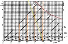
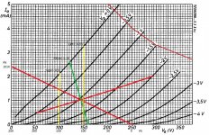
2)I am also trying to design a cathode follower. The load line is shown in picture 2.
The cathode can swing from 72-0 = 72Vp-p
Input voltage swings from 172-254= 82Vp-p
I am trying to find the center bias point.
Would this be half cathode swing or half input voltage swing?
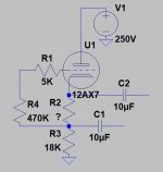
3)Picture 3 is the schematic. For the AC load line I need to calculate Rac.
If I take the output at C1 is this R3 || Rload?
If I take the output at C2 is this R2+R3 || Rload?
4)Output impedance of cathode follower
If I take the output at C1 is this: output impedance 12ax7+R2||18K?
If I take the output at C2 is this: output impedance 12ax7||18K?
Many questions, thank you in advance.
1) Making a load line for 2xel34 in p-p class ab for a Marshall plexi I got the following result( picture 1). Notice how the load line enters the 25W max dissipation curve. I assume the max dissipation curve is for class A and I can average it for p-p.
Does this mean that I can effectively double the max dissipation curve to 50W in p-p since the tube is only there half a cycle? If so, what would happen when also paralleling tubes?
2)I am also trying to design a cathode follower. The load line is shown in picture 2.
The cathode can swing from 72-0 = 72Vp-p
Input voltage swings from 172-254= 82Vp-p
I am trying to find the center bias point.
Would this be half cathode swing or half input voltage swing?
3)Picture 3 is the schematic. For the AC load line I need to calculate Rac.
If I take the output at C1 is this R3 || Rload?
If I take the output at C2 is this R2+R3 || Rload?
4)Output impedance of cathode follower
If I take the output at C1 is this: output impedance 12ax7+R2||18K?
If I take the output at C2 is this: output impedance 12ax7||18K?
Many questions, thank you in advance.
Attachments
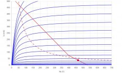
Yes you can cross the dissipation parabola. The answer is not just "twice". Plot the average DC input, subtract the power output, that's what heats the tubes.
WHY?? 18k load on a 12AX7? The tube does not know where the load is. A "good" cathode follower starts with the Resistance Coupled Amplifier Table. For 12AX7 the DC load will generally be 100K or more. The R-C table also tells what is a good external load, though you can shave this some when your signal level is far-far below your B+ level and if THD is not a primary concern. (Happy 12AX7 CF THD will be <0.1% until it goes blatt.)
WHY?? 18k load on a 12AX7? The tube does not know where the load is. A "good" cathode follower starts with the Resistance Coupled Amplifier Table. For 12AX7 the DC load will generally be 100K or more. The R-C table also tells what is a good external load, though you can shave this some when your signal level is far-far below your B+ level and if THD is not a primary concern. (Happy 12AX7 CF THD will be <0.1% until it goes blatt.)
12ax7’s have a hard time conducting enough current to use 18k in the tail. I’m guessing you want 4 to 5 mA, putting about 1/3 of your supply on the tail. That’s what 12au7’s are for. Or sn7, or even bh7. Just costs heater current - electrons have to come from somewhere.
As far as calculating it goes, you can sit and figure it out with a load line and anode curves, but it’s just as easy to breadboard and trim R2 till it’s right. If you use a 2 watt resistor in the tail it will be hard to overload anything.
For power dissipation in output tubes, the max average power dissipated in each side of a class B stage is Vs^2/(pi^2*RL). For AB, quiescent may or may not be higher (use the higher of the two). It simplifies to B+^2/(2.5*Ra-a). It CAN theoretically go higher (to B+/(2*Ra-a)) , but that requires a square wave drive at exactly half the supply voltage. This is statistically unlikely since you only square the wave off if you’re clipping. At clipping the average plate dissipation drops and you need to watch screen dissipation instead. Unfortunately, estimating that is almost impossible unless you go to the trouble of numerical integration using the ig2 curves. You just need to measure it and drop Vg2 if you get in trouble. Many times just increasing the screen stopper resistor is enough. EL 34s are nice because the g2 rating is 1/3 of plate rating. Which is a higher ratio than with most types.
Thanks PRR and wg_ski.
Ok lets do one step back with the cathode follower, I would like to understand better why 18K is not a good value for a 12ax7. ( If only for educational purposes so I can use the knowledge with a better selected tube)
The cathode follower is for the send of an effects loop. I would like to be able to drive a 10K load.
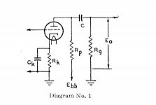
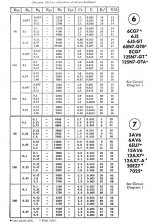
I have been looking at Resistance Coupled Amplifier Tables. One I have found from RCA for 12ax7 shows the two pictures attached.
In my case, Ebb=250, Rp=0, Rk=?, and Rg ( which I see as the loads input impedance) can be as low as 10K.
How do I determine from the RC tables that I need to make Rk 100K or more? How do I see what a good external load is?
Ok lets do one step back with the cathode follower, I would like to understand better why 18K is not a good value for a 12ax7. ( If only for educational purposes so I can use the knowledge with a better selected tube)
The cathode follower is for the send of an effects loop. I would like to be able to drive a 10K load.
I have been looking at Resistance Coupled Amplifier Tables. One I have found from RCA for 12ax7 shows the two pictures attached.
In my case, Ebb=250, Rp=0, Rk=?, and Rg ( which I see as the loads input impedance) can be as low as 10K.
How do I determine from the RC tables that I need to make Rk 100K or more? How do I see what a good external load is?
Attachments
Not digging deeply, just from practical knowledge, 12AX7 are happy passing *around* 1mA.
Say 0.5mA to 1.2 or 1.5 tops, so select load resistors (plate or cathode) accordingly.
Any higher, its sisters aere better suited, as mentioned above.
Say 0.5mA to 1.2 or 1.5 tops, so select load resistors (plate or cathode) accordingly.
Any higher, its sisters aere better suited, as mentioned above.
...Resistance Coupled Amplifier Tables. .... In my case, Ebb=250, Rp=0, Rk=?, and Rg ( which I see as the loads input impedance) can be as low as 10K. ... I determine from the RC tables that I need to make Rk 100K or more? ...
As cathode follower, Rp is the large cathode resistor. None of the 12AX7 suggestions show less than 100k for Rp or Rg (input of next stage) because of poor output and distortion.
It can certainly be done. But hard to start from clean sheet. _I_ would look at how other designers have done this. (Actually, I would use a FET and not tell anybody.)
FWIW, Richard Kuehnel has a rousing loop design analysis in, I think, System Design.
Thanks JMFahey and PRR.
So basically the RC tables do not list my conditions because they do not provide good output or distortion. Hmm what to do next.
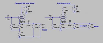
Pic 1 Following PRR's advice I looked at how other designers did this. In M. Blencowe's book I found the two examples shown which were ( almost) approved by the author.
I decided to make a load line for these two circuits, to get some understanding on how they perform.
I am not an experienced circuit designer, as already shown, so I would really appreciate it if someone wants to take the time to validate my findings.
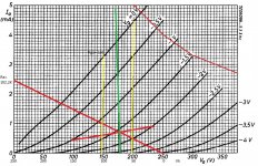
Pic 2 shows the Peavey 5150 loop driver.
Green AC line Rk(ac)= 101K||10K=9.1K
Cathode can swing from 130 to 90=40V
Bias point is at 105v so maximum clean output swing is from
105-90=15Vx2=30V p-p.
Input voltage swings from 120 to 162= 42V
Bias point is at 145 so maximum clean input swing is from
162-142=17x2=34V p-p
This is however not the same in LTSpice, there I can get only about 22V p-p input before clipping.
Pic 3 shows the Engl loop driver.
Green AC line Rk(ac)=2.2K||10K||10K=1.53K
Cathode can swing from 78-72=6V
Bias point is at 74v so maximum clean output swing is from
74-72=2Vx2=4V p-p
Input voltage swings from 171V to 175V=4V
Bias point is at 174 so maximum clean input swing is from
175-174=1x2=2Vp-p
In LTSpice I can put about the same voltage in before clipping, only the output is now reduced to about 1.8Vp-p.
I am expecting gross mistakes in my logic. For now both seem to be able to me to drive a line level voltage of 2Vp-p into a 10K load without clipping.
Because Ltspice shows less gain in the Engl loop driver and it has less headroom, I would go for the Peavey 5150 loop driver.
I appreciate all comments, corrections and insights
So basically the RC tables do not list my conditions because they do not provide good output or distortion. Hmm what to do next.
Pic 1 Following PRR's advice I looked at how other designers did this. In M. Blencowe's book I found the two examples shown which were ( almost) approved by the author.
I decided to make a load line for these two circuits, to get some understanding on how they perform.
I am not an experienced circuit designer, as already shown, so I would really appreciate it if someone wants to take the time to validate my findings.
Pic 2 shows the Peavey 5150 loop driver.
Green AC line Rk(ac)= 101K||10K=9.1K
Cathode can swing from 130 to 90=40V
Bias point is at 105v so maximum clean output swing is from
105-90=15Vx2=30V p-p.
Input voltage swings from 120 to 162= 42V
Bias point is at 145 so maximum clean input swing is from
162-142=17x2=34V p-p
This is however not the same in LTSpice, there I can get only about 22V p-p input before clipping.
Pic 3 shows the Engl loop driver.
Green AC line Rk(ac)=2.2K||10K||10K=1.53K
Cathode can swing from 78-72=6V
Bias point is at 74v so maximum clean output swing is from
74-72=2Vx2=4V p-p
Input voltage swings from 171V to 175V=4V
Bias point is at 174 so maximum clean input swing is from
175-174=1x2=2Vp-p
In LTSpice I can put about the same voltage in before clipping, only the output is now reduced to about 1.8Vp-p.
I am expecting gross mistakes in my logic. For now both seem to be able to me to drive a line level voltage of 2Vp-p into a 10K load without clipping.
Because Ltspice shows less gain in the Engl loop driver and it has less headroom, I would go for the Peavey 5150 loop driver.
I appreciate all comments, corrections and insights
Attachments
- Home
- Live Sound
- Instruments and Amps
- Questions regarding two load lines