For me the greatest benefit by use of a shunt regulated power supply version is the use of very large capacitors directly at the supply input of the signal amp unit - i. e. parallel to the shunt unit (e. g. zener diodes). If I use a serial regulator (the usual solution), this isn't possible without additional steps.
Therefore I prefer shunt regulated power supply versions (except for power amplifiers).
At commercial products such power supplies with parallel regulation are not often to find. An example is the NAD phono RIAA head amp model "PP-2" - go to first PDF file from post #5 under
http://www.diyaudio.com/forums/analogue-source/155449-head-pre-denon-dl-103-a.html
An example for my own idea of such a power supply you will find by the first PDF-file from post #8 under
http://www.diyaudio.com/forums/anal...ences-between-mark-levinsons-jc-1-jc-1dc.html
Some design considerations concerning high voltage shunt regulators for tube applications are here:
https://www.tubecad.com/2007/06/blog0109.htm
I am looking for best possible topology of shunt regulators for line-stages and RIAA stages with op-amps or discrete versions. Especially the distribution of the currents is of interest.
Until now I make a distribution of 50%:50% (fifty - fifty) This means, when the signal stages need approximately 10mA, then I planned for the zener diodes resp. the shunt regulator also 10 mA. But I don't know, whether this consideration is really correct.
Thank you very much for hints and advices to appropriate threads here on diyaudio.
Last edited:
follow threads to the same topic I have found:
http://www.diyaudio.com/forums/diyaudio-com-wiki/164112-shunt-regulation.html
http://www.diyaudio.com/forums/solid-state/11661-regulators.html#post135006
http://www.diyaudio.com/forums/solid-state/23321-regs-shunt-vs-series.html
http://www.diyaudio.com/forums/powe...lated-24v-dc-power-supply-preamp-modules.html
http://www.diyaudio.com/forums/power-supplies/249067-series-shunt-regulated-power-supply.html
http://www.diyaudio.com/forums/diyaudio-com-wiki/164133-shunt-regulation-part-3-a.html
Last edited:
Shunt regulation is fine for EHT voltages, (PD500 glowing blue with Xrays in the Decca series 1 Colour TV, comes to mind) but very inefficient, poor regulation and wasteful compared with series regulation.

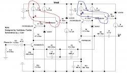
??? The only shunts i see here are the zeners, producing reference voltages for series regulator transistors !Example of Shunt Reg used in the Tomita RIAA:
Mona
From measuring results this is correct. But by listening tests I note better results with parallel regulation together with serial pre-regulator - a single serial regulator like often used 7815/7915 or LM317/LM337 don't provide really good results (in this case I have found also threads here on diyaudio:Shunt regulation is fine for EHT voltages, (PD500 glowing blue with Xrays in the Decca series 1 Colour TV, comes to mind) but very inefficient, poor regulation and wasteful compared with series regulation.
http://www.diyaudio.com/forums/power-supplies/299094-series-shunt-regulator-ziggyreg-v-2-0-a.html
http://www.diyaudio.com/forums/power-supplies/265435-tandem-regulators.html
http://www.diyaudio.com/forums/lounge/146693-john-curls-blowtorch-preamplifier-part-ii.html (go to post #58215 on page 5822) .
Obviously, an extremely high stability of the voltage isn't important for best possible sonic quality - especially in gain stages with low and constant power consumption. Therefore the question rises up, what is most important in a power supply for best possible sound results.
more URLs:
http://www.diyaudio.com/forums/powe...listic-salas-low-voltage-shunt-regulator.html
http://www.diyaudio.com/forums/power-supplies/220734-mr-jungs-new-shunt-regulator.html
http://www.diyaudio.com/forums/power-supplies/229445-high-power-shunt-regulator.html
http://www.waltjung.org/PDFs/UnivReg_122714.pdf
http://waltjung.org/PDFs/AX_WJ_Interview.pdf
http://www.diyaudio.com/forums/power-supplies/37994-power-supply-shunt-series.html
Last edited:
??? The only shunts i see here are the zeners, producing reference voltages for series regulator transistors
Nodes A and B are set to (Vrail - 5.55) volts, by the shunt regulators shown in red and blue, respectively. The shunt elements are Q3 and Q6.
Each shunt regulator forms the first stage of a two stage regulator pair. Shunt regulator Q3 is followed by series regulator Q2, and also shunt regulator Q6 is followed by series regulator Q5. It's very elaborate.
_
Attachments
link is death. Here the text information of this old URL from Mr. N. Thevissen:Hi peranders.
Is this the same trick you talk about ??
http://www.daisy-laser.nl/homeoptics/page32.html
Large capacitors in the power supply
Some words on a simple improvement for many power supplies.
In the High End audio world a lot of effort is put in the power supply. It is a good thing to do. The critical item is the regulator it self. This component needs to be able to handle the large currents, fast and accurate. Fast and accurate correction will lead to supplies who are close to instability. Therefore all regulators have their limitations and are designed to be stable.
Nothing wrong with that as long as we keep it in mind. Increasing the input voltage/current situation does at a certain point no longer improve the output signal of the regulator. Larger transformers, larger capacitors on the input side do not improve the output signal. The regulator will be the limiting factor.
There is however a relative simple trick to overcome this limitation.
In a normal power supply the capacitors behind the rectifier circuit take care of the smoothing of the AC related peaks. After this the remaining voltage/current goes into a voltage regulator and is "cut" to the level required.
The idea of the regulator is to keep this level as constant as possible independent of the amount of current drawn from the regulator by the user. This is a hell of a job if puls shaped currents are drawn.
Small disturbances at the output of the regulator need to be compensated as fast as possible. Pulse shaped currents can be considered as large and fast disturbances. The compensation will not go infinite fast and may also be not a total as this will result in an oscillating power supply.
It would be much better for the regulator if it was buffered on its output side by a large reservoir of electrons in a capacitor. In case the user pulled some current, the level of the reservoir would hardly change in case it is a "large" reservoir.
Here the problem occurs. If the reservoir is empty, it takes a hell of a time to fill it. The sudden opening of the inlet to the reservoir may give the regulator the impression that he never gets the reservoir filled. The result is that the regulator will see a "short circuit" and shut down. Regulators have problems to "start up" mounted in such configurations.
The remedy is however relatively simple.
First fill the reservoir by means of a resistor.
When the reservoir is full then you short circuit the resistor by means of a switch.
The resulting situation is that you have a nice swimming pool of electrons all at the correct voltage level. The moment some are needed, the level will not drop that fast and the regulator
will not have to work so fast to compensate. Actually the voltage disturbances will be smaller. Peak currents are also no longer a problem as they do not need to come fully from the transformer via the regulator. You can do with a lower peak design for your transformer.
Value of the resistor.
If a capacitor is charged via a resistor it reaches after RxC 63% of its maximum level.
After a time of 10 x R x C the capacitor can be assumed to be full.
For a 4700 uF capacitor and a 20 ohm resistor this is 1 second. As a 20 ohm resistor will not pull more then 250mA out of a 5V supply it is a save value to work with.
Now you can use a stack of these capacitors in your 5V supply. If you take 4 of them wait 4 seconds before you close the switch which short circuits the resistor. To compensate for the internal resistance of larger capacitors it is recommended to put parallel to every of these large capacitors a capacitor of 100 nF or 220 nF. Judge it your self.
As you can see it is a simple trick, which saves money for large transformers and very large capacitors on the input side of the regulator and has
a maximum effect on the side where it matters, the output close to the user. Also it is no longer required to use extreme fast and complicated regulator circuits. The actual voltage output of the regulator is not the most important factor 4.9V or 5.1V is not an issue. The stability is the issue and that is solved by the above trick. Therefore simple regulators like the 7805 will do the job.
Found by
https://web.archive.org/web/20040217193329/http://www.daisy-laser.nl/homeoptics/page32.html
This is a very naïve view of a regulator, the 'fast' etc. It is perfectly feasible to design a reg that is fast with respect to the load current changes, and that is what matters. Not whether it is fast in some undefined and unspecified way. Stability is a design thing and easily taken care of.
And even if you have a large cap after the reg, how about looking at how 'fast' this cap is to give up electrons to the load?
Terms like ESR and ESL come to mind which can be and often are orders of magnitude larger than the reg itself, meaning that cap doesn't do diddly.
Jan
And even if you have a large cap after the reg, how about looking at how 'fast' this cap is to give up electrons to the load?
Terms like ESR and ESL come to mind which can be and often are orders of magnitude larger than the reg itself, meaning that cap doesn't do diddly.
Jan
Did I hear naive?This is a very naïve.....
.....Stability is a design thing and easily taken care of.
No, if Q3 and Q6 where shunts there would be a constant voltage on them but that changes with the power voltage.Nodes A and B are set to (Vrail - 5.55) volts, by the shunt regulators shown in red and blue, respectively. The shunt elements are Q3 and Q6.
Each shunt regulator forms the first stage of a two stage regulator pair. Shunt regulator Q3 is followed by series regulator Q2, and also shunt regulator Q6 is followed by series regulator Q5. It's very elaborate.
_
Mona
- Status
- Not open for further replies.
- Home
- Amplifiers
- Power Supplies
- Questions about Shunt Reg's