Ok i've been building and learning the past two months. thank you guys for all your help!  (if you just want to read the question and skip the story it's in red...)
at first i build a valve jr. guitar amp from scrap parts, which works fine.
then i found this dirt cheap PP amp and build some variations on the 18watt marshall design. slightly less of a success due to hum issues...
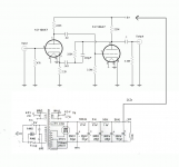
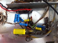
well then I decided to replace my solid state preamp and build a phono tube preamp. I choose this schematic because I had all the parts here. (except for the 3m3 so i used 5x 680k in series) but i don't really know what is good or a better phono design there is just so much information out there
at first i had some trouble controlling the filament hum and tried all suggested methods i could find on this website and others...
after all the most suggested option of the 100ohm resisters in series with the PT worked best so far.
there is still some humming coming from the power transformer and i think this reflects back through the preamp and into the audio signal . i also read about this on different forums but for now i am ok with it. i only hear it when putting the volume at 50%. and normal living room listening would be 25% to 30%.
the phono pre amp is just a start, next step will be the el84 PP or 6V6 PP part of the amp. that's why i used the power supply as you find added to the schematic in the attachment.
now i have some questions about this phono pre amp schematic, it seems to do it's job pretty good, but can somebody please tell me more about how it works in general and also what would be the preferred operating voltage to feed it. could any parts of it be improved?
i looked around at other schematics and they were all around 150 and 160volts and the last part of my power supply provides 162volts and that's what i tested it with.
but if i monitor the power output when i switch of the amp it will work fine until it drops under 90volts..?
i also noticed it is a bit distorted when using my shure m75 cartridge, if i use a stanton 681eee it sound good. this is when used with my dual 1226..
.........
needle
(if you just want to read the question and skip the story it's in red...)at first i build a valve jr. guitar amp from scrap parts, which works fine.
then i found this dirt cheap PP amp and build some variations on the 18watt marshall design. slightly less of a success due to hum issues...
well then I decided to replace my solid state preamp and build a phono tube preamp. I choose this schematic because I had all the parts here. (except for the 3m3 so i used 5x 680k in series) but i don't really know what is good or a better phono design there is just so much information out there
at first i had some trouble controlling the filament hum and tried all suggested methods i could find on this website and others...
after all the most suggested option of the 100ohm resisters in series with the PT worked best so far.
there is still some humming coming from the power transformer and i think this reflects back through the preamp and into the audio signal
. i also read about this on different forums but for now i am ok with it. i only hear it when putting the volume at 50%. and normal living room listening would be 25% to 30%. the phono pre amp is just a start, next step will be the el84 PP or 6V6 PP part of the amp. that's why i used the power supply as you find added to the schematic in the attachment.
now i have some questions about this phono pre amp schematic, it seems to do it's job pretty good, but can somebody please tell me more about how it works in general and also what would be the preferred operating voltage to feed it. could any parts of it be improved?
i looked around at other schematics and they were all around 150 and 160volts and the last part of my power supply provides 162volts and that's what i tested it with.
but if i monitor the power output when i switch of the amp it will work fine until it drops under 90volts..?
i also noticed it is a bit distorted when using my shure m75 cartridge, if i use a stanton 681eee it sound good. this is when used with my dual 1226..
.........
needle
Attachments
My guess is that the Shure gives you more distortion because it has a higher output. The circuit you're using has pretty poor overload margins and the more-than-double output of the Shure could be pushing things. Pay attention to the second stage, which uses grid current biasing, not a great choice.
Best improvements would be topology changes, not parts substitutions. You'll probably want to use a lot higher supply voltage as well- 300V would not be too much. At 160V, the tubes are starving. As well, the heaters could use a better power arrangement, preferably with common mode filtering- grounding one side is an invitation to excessive noise. I'd look at some of the old Marantz and Audio Research circuits which use the same basic tube plus feedback; they are far from optimal, but they'd be a major step up for you. Beware EBay merchants claiming that they sell Marantz clones.
Best improvements would be topology changes, not parts substitutions. You'll probably want to use a lot higher supply voltage as well- 300V would not be too much. At 160V, the tubes are starving. As well, the heaters could use a better power arrangement, preferably with common mode filtering- grounding one side is an invitation to excessive noise. I'd look at some of the old Marantz and Audio Research circuits which use the same basic tube plus feedback; they are far from optimal, but they'd be a major step up for you. Beware EBay merchants claiming that they sell Marantz clones.
Member
Joined 2009
Paid Member
I'm no expert at all - but maybe you can change things around using most of the bits you have - assuming you can put some different valued caps/resistors in ?
for example, rather than using a feedback based RIAA why not a no-feedback passive design.
There's a classic design that has been built and refined that may be of interest:
Orignal design (some say it's good, others say not) 7025, ECC803S, 12AX7A Tube RIAA Phono Preamplifier Schematic
Improvements: http://www.diyaudio.com/forums/tubes-valves/212570-phono-line-stage-project.html#post3021478
Also: The Tube CAD Journal: Passive equalization preamp
Edit: not sure how to solve the low voltage conundrum. Maybe take off a separate feed from the power transformer secondary and make a voltage doubler for the pre-amp.
p.s. I've no experience doing any of the above ideas !
Last edited:
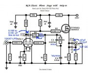
Bigun pointed towards RCA's seminal passive EQ design. Both it and the circuit the OP used have very poor drive capability. I've uploaded a tweaked version of the RCA setup that has good drive capability and better bass extension than the original.
BTW, passive EQ phono preamps have better overload margins than active EQ designs.
BTW, passive EQ phono preamps have better overload margins than active EQ designs.
Attachments
Member
Joined 2009
Paid Member
Lots of good advice already, but I'd just add: Grid stoppers are always good. 1K Ohm's are fine. To replace the grid leak bias, an IR or an ordinary red LED from the cathode to ground works great. You can then remove several of your series'ed 680K resistors; two each channel should be plenty. Should be plenty of output with the better bias.
All good fortune,
Chris
All good fortune,
Chris
Grid leak bias in the 2nd gain block helps in the bass extension dept. The 20 MOhm part lightly loads the EQ network.
Sure does! I'm still thinking along the lines of the OP's original circuit. (Feedback EQ doesn't bug me as much as it does lots of other folks, but I tend to keep impedances very high, to minimize loading.)
One way to do this is the Dick Burwen circuit, which runs the first triode open loop and the second with anode follower feedback for the EQ. Works a treat.
It's surprising how high the impedances can be interstage without contributing significantly to the preamp's noise.
Thanks,
Chris
With diodebias, fixed or cathodebias with 1M to ground you will be able to do within 0,1dB RIAA-correction if you just have components with the proper tolerance. But within 0,5dB is no problem.The 20 MOhm part lightly loads the EQ network.
I´d say 80% of the corrections presented at this forum are incorrect. To get it right one must use something like Hagermans rev-RIAA.
As someone pointed out a red LED 1,6-2V will work for 12AX7.
To get good result with this tube B+ of 400V is needed.
I would suggest you use a 6922 as second tube in a passive RIAA. You will then get acceptable drive capabilities and a gain of just over 40dB.
This is the concept Erik Andersson(Audion, Audio Innovations) and I work on, modernising his old Edison One from the 80´s:
HiFiForum.nu - Edison One 2012
thanks for all your reply's
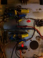
so I had some time to work on the preamp,
wouldn't 400v be to high? I changed the power supply, so the preamp gets 330volt.
ok well, I started with your suggestion cause I had the parts, and if my ears are correct i get some more definition in the highs, overall it's like the loudness is turned on...
i'd still like it to have a bit less gain... the Shure distortion is less but still a bit distorted. (i did check the manual for correct weight settings etc.)
i've ordered some more parts so i can try the other suggested circuit....
thanks again,
Needle
so I had some time to work on the preamp,
To get good result with this tube B+ of 400V is needed.
wouldn't 400v be to high? I changed the power supply, so the preamp gets 330volt.
Lots of good advice already, but I'd just add: Grid stoppers are always good. 1K Ohm's are fine. To replace the grid leak bias, an IR or an ordinary red LED from the cathode to ground works great. You can then remove several of your series'ed 680K resistors; two each channel should be plenty. Should be plenty of output with the better bias.
All good fortune,
Chris
ok well, I started with your suggestion cause I had the parts, and if my ears are correct i get some more definition in the highs, overall it's like the loudness is turned on...
i'd still like it to have a bit less gain... the Shure distortion is less but still a bit distorted. (i did check the manual for correct weight settings etc.)
i've ordered some more parts so i can try the other suggested circuit....
thanks again,
Needle
Attachments
- Status
- This old topic is closed. If you want to reopen this topic, contact a moderator using the "Report Post" button.
- Home
- Amplifiers
- Tubes / Valves
- questions about my ecc83 phono pre build