Hi all tube amplifier master,
I need your kind explanation about appropriate grounding in schematics.
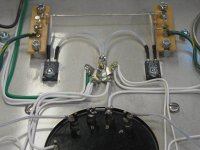
The attached is what my diagram of tube amplifier. From the diagram, could you explain to me for #A through #F for what is going on?
Many thanks and bow to you in advance.
Regards,
Dontellpapa
I need your kind explanation about appropriate grounding in schematics.
The attached is what my diagram of tube amplifier. From the diagram, could you explain to me for #A through #F for what is going on?
Many thanks and bow to you in advance.
Regards,
Dontellpapa
An externally hosted image should be here but it was not working when we last tested it.
from your main earth point take a (black)wire for "c+a"
and then an other (black)wire from your main earth point going to "f "first through to "a"
and then a bit of (white)wire from the "0 ohm tap on the out-put transformer" to point "a"
use about 1mm core wire (or may be a bit less)
try to make the white wire one strand of copper core wire
and then an other (black)wire from your main earth point going to "f "first through to "a"
and then a bit of (white)wire from the "0 ohm tap on the out-put transformer" to point "a"
use about 1mm core wire (or may be a bit less)
try to make the white wire one strand of copper core wire
Thanks Pointy for how to connect all groundings.
I need a help of understanding the logics of all groundings from a through f.
I need a help of understanding the logics of all groundings from a through f.
dontellpapa: Search this forum for "star grounding"
As a general rule of thumb (for star grounding), to reduce hum, you want to tie all of the signal grounds to one common point, which may also be your safety ground, or use one connection to tie the star ground point to the chassis/safety ground if they are not the same point.
Another grounding scheme is buss grounding.
The objective with either scheme is to reduce/eliminate ground loops due to differing voltage potential at the grounding points.
Poindexter has a mini-dissertation on grounding and hum here (about 1/2 way down the page):
THE MUSICAL MACHINE; IMPLEMENTATION.
that was from f to a ........ anyway from your "main earth" to "f"
then from "f" to "e"
then "e" lastly to "a"
and don't forget to bring the white wire from "0 ohms tap of the out-put transformer" to "a" also
this is an old style of earthing and it's true you may find "star earthing" better
then from "f" to "e"
then "e" lastly to "a"
and don't forget to bring the white wire from "0 ohms tap of the out-put transformer" to "a" also
this is an old style of earthing and it's true you may find "star earthing" better
Thanks for all your feedback above.
However, I wanted to understand the reason of the grounding in each location of the diagram above. At least I like to know when/where to place grounding from the diagram.
Thanks.
Dontellpapa
However, I wanted to understand the reason of the grounding in each location of the diagram above. At least I like to know when/where to place grounding from the diagram.
Thanks.
Dontellpapa
Just a quick non grounding related note on your schematic - the LED that you have shown on the primary side will die of excessive reverse voltage (max spec is around 4-5V). You need to put a diode in parallel with it with reverse polarity to prevent this.
put the diode in series with the LED. That will drop the power dissipated in the resistor by half.Just a quick non grounding related note on your schematic - the LED that you have shown on the primary side will die of excessive reverse voltage (max spec is around 4-5V). You need to put a diode in parallel with it with reverse polarity to prevent this.
First I must change the line up I said before ….....................
instead of “0 ohm of the out-put transformer” to “a”
the “0 ohm from the out-put transformer” should go with “d”
OK …..D and F – basics on how the valves work are the hook shape in the bottom of the circle are the cathodes which are small metal tubes which are heated .
When you heat metal it will emit electrons (which have a *negative charge ) then by *magnetism the electrons will be pulled towards the DC *positive anode plate at the top of the circle.
Then the control grid which is the bit between the cathode and the anode plate has the audio signal
played in to it.
So that the control grid will go a little bit positive and then a little bit negative with the audio signal.
When the control grid is negative it will stop the flow of electrons from the cathode to the anode plate.
So the earth point at D and F will give a free supply of electrons to be emitted from the heated cathode (the hook shape bit)
A and E will pull the audio signal more negative which makes the valve (tube) work better........
B is a supply of electrons for the transformer (pulling them up from ground)
and lastly C is a drain for AC current from the power supply unit.
I hope this helps …..................?
Please specify the detail of the diode. Is there any requirement of wattage, impedance or voltage for the diode you mentioned?
put the diode in series with the LED. That will drop the power dissipated in the resistor by half.
True. But it won't solve the problem with the reverse voltage. The diode in series with the LED won't conduct when reverse biased, but the reverse voltage across the LED is determined by the ratio of the reverse leakage of the diode and the LED respectively.
You need a diode (say 1N4007) in anti-parallel with the LED (i.e. anode of LED to cathode of 1N4007) as well as the diode in series with the two to cut the power in the resistor in half. Or better yet... Use a capacitor rather than a resistor. There are examples on the 'net for this. I seem to recall using 220 nF, 1 kOhm in series with a red LED with anti-parallel protection diode as a mains indicator once (on 230 V).
~Tom
Here'a one option
I use a star ground, which is all the grounds to a single point. The reasoning behind this is simple. When the current return path of every circuit is connected together at a single point, the current loop of each circuit stays in it's own circuit. In other words, there can be no shared current, thus no crosstalk, of signal, noise, or DC, from one circuit to another through a single point (including externally coupled circuits). Works for me.
Michael
PS Your schematic is missing the 3rd wire safety ground in the mains connection
Hi all tube amplifier master,
I need your kind explanation about appropriate grounding in schematics.
The attached is what my diagram of tube amplifier. From the diagram, could you explain to me for #A through #F for what is going on?
Many thanks and bow to you in advance.
Regards,
DontellpapaAn externally hosted image should be here but it was not working when we last tested it.
I use a star ground, which is all the grounds to a single point. The reasoning behind this is simple. When the current return path of every circuit is connected together at a single point, the current loop of each circuit stays in it's own circuit. In other words, there can be no shared current, thus no crosstalk, of signal, noise, or DC, from one circuit to another through a single point (including externally coupled circuits). Works for me.
Michael
PS Your schematic is missing the 3rd wire safety ground in the mains connection
Attachments
Last edited:
but the reverse leakage of the diode is so small that any reverse conduction of the LED will drop the voltage and current well below anything that can damage the LED.But it won't solve the problem with the reverse voltage. The diode in series with the LED won't conduct when reverse biased,
It just needs a diode and LED and resistor to operate across the mains.
But be careful that is exposed to mains voltage.
- Status
- Not open for further replies.
- Home
- Amplifiers
- Tubes / Valves
- Questions about grounding