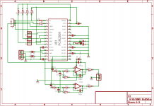
Good choice! The PCM2906 and the OPA2353 sound very good together.
About the DC coupling in output, I suggest you to place in the schematic and PCB the space for the output capacitors.. if you see that there is no offset you can safely remove the capacitors and replace them with wires.
I have not studied your schematic, but remember that you are supplying the opamps between GND and 5V..
This is how I realized more or less the same schematic (with also input buffer and regulator):
(click to enlarge)
(click to enlarge)
Bye,
Paolo
About the DC coupling in output, I suggest you to place in the schematic and PCB the space for the output capacitors.. if you see that there is no offset you can safely remove the capacitors and replace them with wires.
I have not studied your schematic, but remember that you are supplying the opamps between GND and 5V..
This is how I realized more or less the same schematic (with also input buffer and regulator):
An externally hosted image should be here but it was not working when we last tested it.
(click to enlarge)
An externally hosted image should be here but it was not working when we last tested it.
(click to enlarge)
Bye,
Paolo
paologatto said:I have not studied your schematic, but remember that you are supplying the opamps between GND and 5V..
This is how I realized more or less the same schematic (with also input buffer and regulator):
Yes, that is why I wondered... 🙂
But, the inverting inputs to the opamp gates are polarized by C11 and C17. So I was hoping that would nullify any DC on the output.. 🙂 I guess I will just have to do as you say and check. 🙂
BTW your DAC is very nice!!! 🙂 Good work!!!

- Status
- Not open for further replies.
