Some background.
The project it is to power...
https://www.diyaudio.com/community/threads/diy-front-end-2022.394339/
The supply board..
https://www.diyaudio.com/community/...4-tl072-regulator-based-on-studer-900.297610/
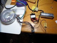
The transformer..
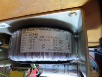
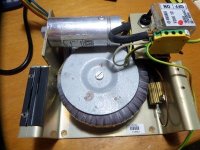
(Probably total overkill but I own it and can't afford any other) A Muuntosahko-Trafox TAE-160. 230v in 2x22v out. (one rated 2amp the other 5amp) 160VA
Seems this Finnish manufacturer makes high spec Transformers for industry and medical.
The Transformer and associated parts include a large 'Prefilter" that I am assuming is the industrial version of the noise filter found on many consumer items chassis mount ac input. Yes/No ?
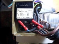
In addition to the input and output wires the transformer has a transparent input wire that is coupled to the ac input cable earth. It is labelled S and SP. What does this connect to/do within the transformer ?.
The mains ac cable goes from the Prefilter to the switch. Both P & N are switched with the N going to the transformer but the P going to Power Resistor in series with the transformer. 7.5R @ 25W.
Why ? What does this do ? Can I omit it in my build ?
Finally, I've seen comments that a too big transformer can be as problematic as too small but never any explanation for this. Is it a real thing ?
The project it is to power...
https://www.diyaudio.com/community/threads/diy-front-end-2022.394339/
The supply board..
https://www.diyaudio.com/community/...4-tl072-regulator-based-on-studer-900.297610/
The transformer..
(Probably total overkill but I own it and can't afford any other) A Muuntosahko-Trafox TAE-160. 230v in 2x22v out. (one rated 2amp the other 5amp) 160VA
Seems this Finnish manufacturer makes high spec Transformers for industry and medical.
The Transformer and associated parts include a large 'Prefilter" that I am assuming is the industrial version of the noise filter found on many consumer items chassis mount ac input. Yes/No ?
In addition to the input and output wires the transformer has a transparent input wire that is coupled to the ac input cable earth. It is labelled S and SP. What does this connect to/do within the transformer ?.
The mains ac cable goes from the Prefilter to the switch. Both P & N are switched with the N going to the transformer but the P going to Power Resistor in series with the transformer. 7.5R @ 25W.
Why ? What does this do ? Can I omit it in my build ?
Finally, I've seen comments that a too big transformer can be as problematic as too small but never any explanation for this. Is it a real thing ?
Attachments
Last edited:
Can't have a too big transformer...the power resistor is for a soft start it should be shorted when power is up after a short delay. Toroid transformers have very low impedance and pass the short the filter caps are at start up to the line and can pop fuses, etc. Not sure what the s and sp are for, maybe a temp sensor or being medical it might have something to do with isolation sensing.
That was my first thought but there is absolutely no other connections that would facilitate this. All cabling is covered/insulated totally to respective terminals and no evidence of any extra circuits. The resistor appears to be in circuit at all times.the power resistor is for a soft start it should be shorted when power is up after a short delay.

If the S/SP is just one wire, it's likely a static shield that lives between the primary and secondary windings. Its pupose is to reduce noise transfer to the seconday and as you mentioned, it is normally connected to the frame ground.In addition to the input and output wires the transformer has a transparent input wire that is coupled to the ac input cable earth. It is labelled S and SP. What does this connect to/do within the transformer ?.
If it's two wires it could be a thermal fuse or switch used to protect the transformer from overheating.
Have you tried searching for the mfgs data sheet for the transformer?
As for the resisitor, the transformer will work fine without it, and if inrush current is a problem, a better solution is to replace the resistor with an NTC thermistor.
Thank you both. That solves my queries.
Yes the transparent wire is single so a static shield connection, Never seen one before, though never had a transformer of this quality before.
I guess the S and the SP labels are 'static' and 'static protection' then.
I will remove the current limiting resistor and continue.
I tried for the data sheet before originally posting but that model is not listed and they seem to have a 'specials to order' service for outside supply. (hence the 2x22v but different current ratings)
Oops... Now that I examine the transformer more seriously I note the primarys are 2 x110v in series so 220v input.
Our mains voltage is 230v +/- 5%. Would the 7.5R 25W resistor in series with the primary be a dropper to shed the 10v overvoltage ? and if so then what consequences, other than a rise in secondary voltage , would occur if removed ? Heating ?
(In years past much of our imported HiFi components were Japan sourced and the voltage selectors only 110 or 220v and worked O.K. though I think the regs have changed since then.)
With the current required by the FE2022, the resistor will do essentially nothing, remove or leave in place as you like.
You really should build a gainclone or other power amp with that transformer, it’s silly amounts of overkill for a linestage. However there are huge points awarded for using parts on hand, so go for it.
You really should build a gainclone or other power amp with that transformer, it’s silly amounts of overkill for a linestage. However there are huge points awarded for using parts on hand, so go for it.
Thanks @6L6 I am rearranging the layout and will test with the resistor both in and out.
Yes... this transformer deserves a bigger project but may well be the useful filler until I find something else more suitable and can free it up.
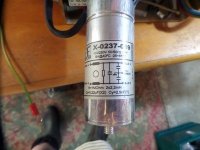
I found some more reference numbers for the supply and it is from an air-particulate-ir-measuring device( with heater circuits.)
I now realise that I have driven past this testing array on my way into work several times
VAISALA FDW13 MAINS POWER SUPPLY
for FD12 and FD12P VISIBILITY METER
The FDW13 Mains Power Supply converts the mains voltage to 24 VAC power for the FDS12 regulator
and the heater elements. The FDW13 includes also the mains voltage selector and the mains ON/OFF switch,
which also functions as an automatic fuse.
😎
Yes... this transformer deserves a bigger project but may well be the useful filler until I find something else more suitable and can free it up.
I found some more reference numbers for the supply and it is from an air-particulate-ir-measuring device( with heater circuits.)
I now realise that I have driven past this testing array on my way into work several times
VAISALA FDW13 MAINS POWER SUPPLY
for FD12 and FD12P VISIBILITY METER
The FDW13 Mains Power Supply converts the mains voltage to 24 VAC power for the FDS12 regulator
and the heater elements. The FDW13 includes also the mains voltage selector and the mains ON/OFF switch,
which also functions as an automatic fuse.
😎
Last edited:
I have everything up and running though sailing close to if not over the wind.
The 22v out from the transformer is 26.5v unloaded and the Frontend2022 circuit draws so little that the loaded voltage is the same.
Unfortunately this exceeds the max 24v allowed for the Studer regulator board and at 37v dc is above the supply capacitor 35v rating.
So, went hunting in the rat-pile and found 2 identical transformers (much lower VA) that I have yet to measure but somehow I recall they may be 20v out.
The Studer circuit requires 2 separate inputs ( usual dual outputs from a single transformer ) and then can be combined at the dc output to give a +++0--- out.
Question, can the same be done using 2 identical transformers, each supplying the Studer as separate inputs but combined at the output.?
(i.e rather than 2 separate windings feeding from the same transformer instead 2 separate windings each from 2 separate transformers.)
Latest version , having scrounged deeply the rat-pile (ratted commercial boards or previous builds no longer needed) I have found a good pair of bridge rectifiers and their heatsink ( what, ! a heatsink for plastic package bridges?) and a pair of LM350 regs I made and forgot... I can now use the found transformer, rectify and regulate each individual winding through the LM350's to a voltage acceptable to the https://www.amazon.ca/Regulator-Reference-STUDER900-Assembled-Finished/dp/B09SVL9HDP and get a clean 24+-0-24- out for the Frontend2022 boards. Phew!
Will report if working 🙂
Will report if working 🙂
- Home
- Amplifiers
- Power Supplies
- Questions about a found transformer