thanh said:Hi fab! My name is thanh ,not than ,not thahn.🙂
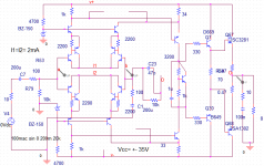
My input stage is a symmetrical cascode diff stage.I use a schematic which you have posted at "hafler mod" etc but i use zener diode instead of 2 resistor
A! I use all 2SC1815/2SA1015
Hi thanh
(sorry for the typo in your name when I respond to post it is sometimes late in the evening after a long day...)
If you use a symetric input stage then you must have also a symetric VAS stage and it is maybe this one or something else that makes the amp to oscillate. Also, have you included the proper essential RC frequency compensation network in the diff stage collector resistors?
Fab
Ah! not yet! So how can i do?Also, have you included the proper essential RC frequency compensation network in the diff stage collector resistors ?
thanh said:
Ah! not yet! So how can i do?
See http://www.diyaudio.com/forums/showthread.php?postid=358442#post358442
in attached circuit. R12 + C4, R19 + C5 form the RC network across the collector resistors of the diff input stage. In the refered circuit, R = 220 and C = 1nf when in parallel with collector resistor of 2k2. Of course, this is only typical value that will change depending on the parameters of the circuits forming the amp. The goal is to reduce the gain at high frequency where the phase shift is high.
Or you can also use a miller cap in the following VAS stage.
Good luck
Fab
i really don't think cfp diff pairs without emitter degeneration is a good idea - never use cirucits that depend on hfe matching for good behavior
Hi jcx ! 🙂 how are you ? 🙂 🙂 .yes , the unbalance of CFB cause wrong biasing . I added degen resistor ,stopper resistor for cascode . Noise was throw away but amp still ocsilate . I don't want to add compensate cap .So I have just removed CFB .
In the sim input stage with cascode can't increase OL BW and I don't feel the difference of cascode sound in the real world . Perhaps I use 1K collector load at input stage and with 1K OL BW is so wide that I don't need cascode for input stage
In the sim input stage with cascode can't increase OL BW and I don't feel the difference of cascode sound in the real world . Perhaps I use 1K collector load at input stage and with 1K OL BW is so wide that I don't need cascode for input stage
Question about CFP
I make an amp with +/-35Vrail supply.
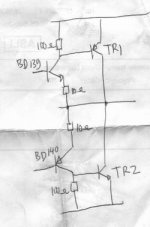
The output stage is like the attachment. The driver is BD139/140, and the final is TR1 and TR2.
If I put TIP35c/36c for TR1/TR2, everything seems ok, no oscilation.
The strange thing is, when I put 2SC2922/A1216 for TR1/TR2, it starts to oscilate, even with no signal.
And when I put 2SC5200/2SA1943, the same amp become an oscilator.
What makes it oscilate with one type of transistor and not oscilating with another one, while everything else is exactly the same? I read in the datasheet, the Fe is different, about 25Mhz for C5200, 30Khz for sankens, and only 3mhz for TIP35c. The capacitance is about the same (200pF) for C5200 and sankens (dont know the data for TIP35C). Is one of these factors make the oscilation?
How to advoid the oscilation, like when using 2SC5200 pairs, but wanted to have stability like when using TIP35C pairs?
I make an amp with +/-35Vrail supply.
The output stage is like the attachment. The driver is BD139/140, and the final is TR1 and TR2.
If I put TIP35c/36c for TR1/TR2, everything seems ok, no oscilation.
The strange thing is, when I put 2SC2922/A1216 for TR1/TR2, it starts to oscilate, even with no signal.
And when I put 2SC5200/2SA1943, the same amp become an oscilator.
What makes it oscilate with one type of transistor and not oscilating with another one, while everything else is exactly the same? I read in the datasheet, the Fe is different, about 25Mhz for C5200, 30Khz for sankens, and only 3mhz for TIP35c. The capacitance is about the same (200pF) for C5200 and sankens (dont know the data for TIP35C). Is one of these factors make the oscilation?
How to advoid the oscilation, like when using 2SC5200 pairs, but wanted to have stability like when using TIP35C pairs?
Attachments
I read in the datasheet, the Fe is different, about 25Mhz for C5200, 30Khz for sankens, and only 3mhz for TIP35c. The capacitance is about the same (200pF) for C5200 and sankens (dont know the data for TIP35C). Is one of these factors make the oscilation?
The faster the transistors are the more they are sensitive to oscillations. A solution helped me with the same problem was to connect a zobel to the ground on the output and also connecting a small capacitor of about 100pF - 1nF between the bases of the output power transistors.
Hi, Bocka,
You happens to experience the same thing? Thanks for the solution, I will try it. You mean from base of C5200 bridging to base of A1943?
I've tried 100pf-100nf accross the 10ohm, accross the 100ohm, from B-E, from B-C, from C-E, makes little effect, cannot cure 100%.
Do you know how to slow down the C5200 from 25mhz to about 3mhz (like the TIP35C)? One strange thing is, while C2922 is faster than C5200, why it oscilates less?
Besides accross bases of A1943 base of C5200, what else can help this?
ft varies over collector current and slightly over production lots. If you want to slow down the the transistors you have to insert a pole somewhere. As the CFP is a two stage amp with 100% feedback, oscillation can occur easily if both transistors have equal fts, as each shifts the phase in the same order of magnitude. A dominant pole in your system results in about 90° phaseshift by approximation at V=1.
Sometimes curing oscillations can only be done by try and error (although I don't like this method...)
Sometimes curing oscillations can only be done by try and error (although I don't like this method...)
Aha, Bocka thanks 😀
Do you mean that the driver (BD139/140 that I use) should be faster than the C5200, so the CFP is harder to oscilate?
I don't know if I capture you right, but the above makes very sense to me. If the C5200 is faster than BD139, it will oscilate easily, offcourse 😀
Do you mean that the driver (BD139/140 that I use) should be faster than the C5200, so the CFP is harder to oscilate?
I don't know if I capture you right, but the above makes very sense to me. If the C5200 is faster than BD139, it will oscilate easily, offcourse 😀
Every feedback loop, however local, needs a dominant pole! it's no good to increase the Ft by an order of magnitude with a different device and expecting it to still perform without oscillation. You must degrade it until it performs like the (cheaper) slow one!
cheers,
Greg
cheers,
Greg
Hi, Amplifierguru,
The one I used is like in post #71, for each half consisting only 1 driver, 1final, and 2 resistors (10+100ohm)
I know you mastered this thing (you know, the A1-A2 thing 😉 ).
If I take the driver as A1 and the final as A2, then it goes the same thing with your A1-A2, where A2 should be slower, not faster, otherwise A1 will not be able to control what happens with A2.
For instance, if the driver is only 5mhz, the final is 30mhz, if there is some disturbance that makes the final amplifies signal, say 15mhz, the driver cannot makes local feedback in the whole CFP for that 15mhz signal, because it is out of the reach of the driver's ability.
How to make a pole with these 4 components (for each half), while the driver is slower than the final stage?
NPNs in high i application
One of the main uses of the Saklia is in an attempt to remove high I power NPN devices.
A quick look at the specification of these devices in comaprison to their PNP counterparts shows that the CBP at high I is significantly lower.
for example at 7A (VCE5V):-
MJL21196 - 1.5
MJL21195 - 3.1
Now this doesn't sound like a lot but it equates in typical audio outputs to an NPN not being able to make audio bandwith at full power.
In a regulator circuit it equates to loss of control at HF.
Now George Sziklai proposed it as an output configuration, not as a low power pair. This followed his 'invention' of the push pull pair and his work with Lin that lead to the "defining" configuration for an audio amp he used it cos they couldn't get any power transistors worth a jot.
We all recognise that it can osillate like hell. It does have some issues asociated with the turn on of the pair. However a lot of the 'bad press' is assocaited with it's misues over the years.
Brian
(feeling good today cos we just shipped my 14 Millionth product)
lumanauw
give a cap parallel to those 100R if you want to slow down the driver section.
But I think zobel network may be usable here instead as mentioned before.
Driver is nearly always faster cause both in CFP are common emitter stages and driver has lower voltage gain, so suffers less from miller effect.
give a cap parallel to those 100R if you want to slow down the driver section.
But I think zobel network may be usable here instead as mentioned before.
Driver is nearly always faster cause both in CFP are common emitter stages and driver has lower voltage gain, so suffers less from miller effect.
- Status
- Not open for further replies.
- Home
- Amplifiers
- Solid State
- Question(s) about CFP.