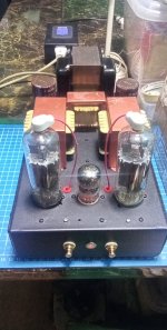
I just picked up a non-functional, home built, 6L6GC push-pull amp for small money because I wanted the output transformers and telefunken 12AX7s. I repaired it and thought I’d gave it a quick listen first before I part it out. I’ve attached a shot of my wiring diagram. My concern is about the way the pentodes screen grids are wired. I assume the builder wanted to build a triode connected PP amp. In my experience the the screen grid pin is wired directly to the plate pin or alternatively connected with a 100R resistor. In this build the screen grid is connected to B+ without a screen resistor. In other words it’s connected to the same node as center tap of the primary side of the O/T. What am I looking at here?
Attachments
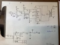
What you're looking at is a pentode connected pair of 6L6's, not triode strapped. You're assumptions of how a pentode grid is strapped is correct. In this case the screen is not cared for and should not have excess high voltage. It's a cheap and dirty way of doing things. Vintage USA made 6L6GCs would stand a good chance of surviving, but not with today's junky chicom or russkie tubes.
Thanks Hollow State. Adding a screen resistor would then be advisable, if I understand correctly. Perhaps design for 270 volts at the screen?
A general rule of thumb for the screen of a power output tube is to be at a lower potential than the plate is. This is for pentode service. For triode connection or ultra linear service this obviously doesn't happen. The screen controls the tube's gain just as much as the control grid does. Thus it also controls plate current (dissipation) which should be kept below max for decent tube life. That's thirty watts for a 6L6GC. So reducing the screen voltage would be advisable. When using a resistor, an electrolytic capacitor for the screen bypass is also advisable because a varying screen potential causes distortion through non linear operation. A capacitor helps to stabilize the screen voltage. And in your case even 300 volts would be okay figuring 380 on the plate. (round numbers) And I've seen even lower ratios in amplifiers. Remember that mostly everything is a tradeoff in design between performance, longevity, cost, availability, etc.

It is a Plain Jane PP 6L6 amp running Class A. Plate current in a Class A stage normally doesn't
change much so PS regulation is not a priority. As a result the B+ can be conveniently lowered
quite a bit by increasing the resister in series with the Power Transformer Secondary to a value
that gets what you need. Start by trying something like 100R, The final resister used will need to
dissipate something like 10 watts.
An often recommended addition is a 1/2 watt resister of 1 to 5K on all the control grids
soldered as close as possible to the tab on the tube socket.🙂
So many people mistakenly call the 6L6 a Pentode.
If you tried to sell a 6L6 by representing it as being a Pentode (it first came out in 1936), you could be in court for a patent law violation.
Pentodes have Suppressor screens.
Beam Power tubes have Beam Formers.
I can not remember the total number of elements in a Traveling Wave Tube.
If it has 3 elements, do you call it a triode?
If it has 4 elements, do you call it a tetrode?
If it has 5 elements, do you call it a pentode?
No, you call it a traveling wave tube.
For those who have forgotten, the 6L6 has a Metal envelope.
The 6L6-G, 6L6-GA, 6L6-GB, and the more powerful 6L6-GC all have glass envelopes.
Just being my picky self tonight.
Today I added a 820R 18w screen resistor, because that’s the only value I could find in the right ballpark at the required power rating. That got my screen voltage down to 290. I was a bit surprised to see the B+ rise to 400. Apparently the idle current has dropped. I didn’t have the opportunity to put it on the scope or do any further testing.
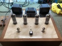
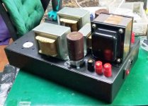
From the photos you can see that this is not an especially promising project given the too large and wooden chassis and undersized power transformer. I intend to learn what I can and move on. It’s a bit noisy; I attribute that to a lack of method to the star grounding. I’ll work through that and measure the changes. It’s only putting out about 12 watts before the waveform starts to getting ugly. I probably won’t bother with grid resistors.
The O/Ts are what attracted my attention. I think they might be from a 7591A amp or receiver. The codes stamped on the bells are T991-116-1G. The EIA might be 926-1177 but the third digit is hard to read. The turn ratios were 40, 27 and 20. 928 is Acme Coil and Transformer; that’s a possibility. Is that familiar to anyone?
Attachments

Last edited:
6A3sUMMER you are being picky. A pentode has five elements. A cathode, control grid, screen grid, suppressor grid/beam forming element and a plate. That's five elements. Penta from the Greek meaning five. Strictly speaking the shape of the 4th element is not what designates a pentode. And yes, I know that many folks over the years like to call some pentodes beam tubes or beam forming pentodes. That's okay because it further describes what one's talking about. I learned about tubes when I was in grade school long before any pentode was called a beam tube. I guess I've been dodging the patent laws for almost a lifetime. 🙂
Turns ratio of 27, with 8 Ohms on the secondary, has about a 5,800 Ohm primary.
The 40 relates to 16 Ohm, the 20 relates to 4 Ohm, again with a 5,800 Ohm primary.
Nice looking transformer!
If you reduce screen voltage, of course the plate current goes down (so does the screen current, and so does the cathode current).
Reduce the 680 Ohm cathode resistors, and you will get more current.
And, whan you reduced the screen voltage with less current on the B+ supply, the supply voltage went up.
According to your schematic, the concertina phase splitter is biased at 0V grid to cathode (could be one reason for early clipping).
No elevated filaments . . . that could be the reason for the hum, cathode to filament breakdown (becomes a resistor, like 100k on its own, and also could be a reason for the early clipping.
Last edited:
Actually the filaments are referenced to one of the power tubes cathodes. It’s C on the drawing. How could I improve the concertina grid to cathode circuit?
Edit, I see what you mean. The concertina needs a voltage divider and a cathode resistor. I’ll check tomorrow to see if I have that drawn right or if it’s lacking.
Edit, I see what you mean. The concertina needs a voltage divider and a cathode resistor. I’ll check tomorrow to see if I have that drawn right or if it’s lacking.
Last edited:
HollowState,
I first learned about vacuum tubes in 1956.
Then I wrote an 8th grade paper called "The Theory and History of Vacuum Tubes" in 1958. I got a B-, but it was for the not-so-good english.
I do remember Beam Power tubes, and Pentodes back then, but I was educated by the 1956 ARRL "Radio Amateurs Handbook".
A tube fan wants to tube roll his Pentode EL34 Amplifier, but he can not find any similar tube, darn it!
Along comes the 'Kinkless Tetrode', the KT77.
Then called a 'Beam Tetrode'.
Then called a 'Beam Pentode'.
The KT77 has beam formers.
Tetra from the Greek meaning four . . . Four elements?
Confusing, yes.
The earliest data sheet I could find from RCA called the 6L6 a 'Beam Power Amplifier' (metal shell case, not a glass envelope).
Later in 1954, RCA's data sheet for the 6L6 and 6L6-G called it a 'Beam Power Tube'.
What's in a name anyway?
Last edited:
Adding a 3.3k cathode resistor to the concertina phase splitter sorted out the issues I was having with the signal shape at higher voltage swings. Thanks for the tip. I recall being puzzled when I sketched the schematic but forgot to follow up.
I also cleaned up the grounding, creating a loop exclusively for the power supply and then connecting that to the IEC plug. I also separated all the transformer grounds (recall it’s a wood chassis) and connected them to the IEC plug ground. The result was remarkable. Both channels measure below 1mv ac. The right channel is almost dead silent and the left is inaudible from a few inches. This is a night and day difference.
The amp is producing about 20 WPC now but any further increase in idle current causes a precipitous drop in voltage. I’m down to less than 350v B+ now. The small transformer is at its limit. I have a 10 lb power transformer that is just perfect for this application right down to the correct secondary voltage. I can even use the existing voltage doubler. I intend to swap that in and see if I can get a stable power supply and a few more watts.
It’s tempting to wire this for triode operation too. The tubes that came with it are a fresh set of JJs. If I were to do this, the plates and screens would hit 450v at start up and then operate at about 400v. I am a bit doubtful that the JJs screen grids will actually withstand that screen voltage for long. I don’t mean to hate on JJs but I’m just a sceptic. Any thoughts on this? I could always find them a nice home in a guitar amp🙂
Those output transformers with T991-1 are, I believe, from Fisher 500c and 800c receivers. Not sure if the "G" on the end makes them a different version. The Fisher service manuals show T991-116-1 or -2. Should be good stuff.
John
John
I just picked up a non-functional, home built, 6L6GC push-pull amp for small money because I wanted the output transformers and telefunken 12AX7s. I repaired it and thought I’d gave it a quick listen first before I part it out. I’ve attached a shot of my wiring diagram. My concern is about the way the pentodes screen grids are wired. I assume the builder wanted to build a triode connected PP amp. In my experience the the screen grid pin is wired directly to the plate pin or alternatively connected with a 100R resistor. In this build the screen grid is connected to B+ without a screen resistor. In other words it’s connected to the same node as center tap of the primary side of the O/T. What am I looking at here?
i say yes to that individual cathode resistor bias on the 6l6 cathodes....
your 6.3vac ct filaments can simply be connected to psu ground and ditch that led in there.....triode mode is simply connecting pin4 to pin3 by a 100 ohm 1/2 watt resistor and disconnecting to A.....you get lesser power but you may like it...try disconnecting that feedback line and try a cap bypass on the 3.3k resistor, a 4.7ufd/16vecap is plenty..
that 100ohm series resistor can be split into 2 47 ohms resistor and add another filter cap for an RCRC filtering, much better than what you have now...
Thanks for those suggestions Tony. The LED is there just to indicate that power is switched on; it’s kind of handy. I will bypass that cathode resistor. I have some nice muse 22uf. Good idea on the filter, why not?
in triode mode, you can get away with no global feedback...i once made this all pentode amps using the 40kg6 and 6bn11 combo...no global negative feedback although i made provisions for it, when i listened to it the first time, i decided not to connect the gnfb line...
Attachments
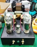

Just to follow up, I removed the screen grid wiring and replaced it with 220R resistors between plate and screen pins so as to triode connect the 6L6GCs. I installed one of those big 200 watt Woodward-Schumacher transformers https://www.diyaudio.com/community/threads/10-pounds-of-power-for-15.169867/page-2 in place of the original and undersized organ transformer.
It’s actually 18 lbs and 200w but with a 110v primary spec, so I used an unnecessary filament winding to buck it to a 120 primary. I’m getting 6.39 vac on the center tapped filament and a 400v B+.
I added the cathode resistor bypass cap on the first stage and measured the result. Without the cap, clipping was first observed on the scope at 0.63 vrms from the signal generator and .35 vrms after the cathode resistor was bypassed. I simply don’t need that much additional drive so the resistor will remain bypassed.
It develops about 9 volts rms across an 8R load befor clipping. About 10 watts. It can drive rather insensitive speakers in a good size room to a pleasant listening level but of course it won’t rock a big party. It sounds quite nice with plenty of bass, very nice guitar and horns. Female vocals seem a bit remote, perhaps pushed into the background a bit, but I’ll need to do some more listening to get a better feel for that criticism. I have a SET and an ULPP running similar pentodes that I want to compare it to in the coming days.
It’s been good fun so far but I will think about building a screen regulator and perhaps set it up as a pentode connected PP (no UL windings) with a 250 volt screen supply. I like the Maida regulator SY used in the Red Light District amp as an option for that. I think I even have some Maida PCBs around here somewhere.
I‘m also a bit curious why I don’t see zener diodes used in screen grid circuits? Why not just slap on a 150 volts worth of zeners and call it a day? Any thoughts?
Last edited:
- Home
- Amplifiers
- Tubes / Valves
- Question regarding wiring pentodes as triodes