I hope I'm not out of line by posting this topic here. It's a little out of context, but does involve building with tubes, so I figure it's OK as long as I make such posts a rare distraction. I prefer the pool of knowlege here to some that I've found in some guitar amp forums. That said...
I've been working steadily at "designing" my first tube guitar amp - mainly by studying classic schematics and applying the humble amount of knowlege I've gained by building tube home audio amps.
In studying the classics, I see that it is common to take the HV for the output tubes' plates directly from the first cap after the rectifier, which results in a ripple voltage that is several volts peak to peak.
Common hi-fi wisdom asserts that this is a highly unwanted characteristic.
My questions are:
1. Is this ripple voltage simply an acceptable feature in guitar circuits, OR...
2. is it allowed because it electrically contributes to the circuit the desired sonic end result that is characteristic of guitar amps?
I'd like to get this ironed out before I start building.
Your help is appreciated.
Adam
I've repaired a few old guitar amps and all of them had the plate connected to the first cap as you describe (PP only, SE it's a no-no). Some of them measured 20V of ripple. It is best to use a matched pair for the output tubes to maximize common mode rejection. In general, the older guitar amps have quite a bit more hum than a Hi-Fi amp, or newer production guitar amplifier.
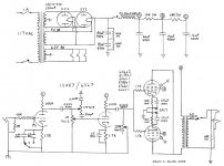
That's what I figured. The image I've attached is an example of a classic SE design that takes the plate supply directly from the first cap.
My first design will be a parallel SE. I'll run the B+ through a CLC before it hits the plates. I'll post the schematic when it's done.
Thanks for the reply.
Adam
My first design will be a parallel SE. I'll run the B+ through a CLC before it hits the plates. I'll post the schematic when it's done.
Thanks for the reply.
Adam
Attachments

At least it's Pentode wired in that schematic. In transformer coupled stage Pentodes have much better ripple rejection than Triode. But I still would not even think about running the plate off the first cap. That's a good idea to run it through a CLC first, as you said.
It is common to feed the B+ to the output tube directly from the first cap. This is usually a matter of economics, maximum power output for minimum money. There is indeed significant ripple in the B+ on many old guitar amps. Almost all guitar amps use a pentode wired output stage. A pentode is far more immune to ripple on the plate voltage, since the plate current doesn't change much with variation in the plate voltage. P-P is also more immune to ripple since some of the hum tends to cancel. The screen voltage must be clean, hence a fairly large resistor, and another cap to feed the screen voltage.
The Champ gets away with it because the output stage is a pentode, and the OPT and speaker roll off the low frequency response. Triode wire a Champ type amp and it WILL hum. Been there, done that, added a choke and another cap.
If you are building a maximum power P-P guitar amp, the plate voltage from the first cap connection is usually OK. I have used it many times. Another factor in a "cranked to 11" guitar amp is power supply sag. The filter caps are smaller than you would find in a HiFi amp, and a lossier rectifier tube is used (5U4 or 5Y3). When the amp is set on kill and the guitar is whacked the power supply voltage drops due to the sudden current demands. The voltage drop affects the preamp stages as well as the power amp. The power amp distorts, but the preamp loses some gain. As the note dies out (less signal from the guitar) the amp starts to come out of severe clipping, so the tubes demand less current, and the B+ voltage begins to rise. This brings back some of the gain to the preamp. This built in compression effect gives the amp its "sustain". A good guitar player with the right amp can modulate this effect by using the volume control on the guitar, and his playing style to change the tone and dynamics of the sound without affecting the overall volume since the amp is saturated. Big fat caps, a 5AR4 or a SS rectifier tend to kill this effect, but may allow more peak power, so it all depends on the desired effect.
The power supply, audio coupling cap size, amount of preamp gain, tone stack design, and application of feedback are the usual "knobs" that you have to play with when designing a guitar amp. Of course the speaker is the biggest "knob". Unfortunately is is a matter of experimentation to find just the right sound, and the right sound is (as in HiFi) a matter of personal preference.
I have also built some "HiFi guitar amps" for clean sound and acoustic guitar. I use the traditional HiFi design techniques, and even a HiFi type speaker. This type of amp is of no use to the typical metal head, it doesn't "crank".
Thanks, TubeLab - informative as always. To begin, I'll use some moderately fat caps and a pair of lossy rectifiers in series. I've never heard a guitar amp with a vacuum rectifier, let alone a directly heated one. Luckily, I have a large stash of all types and am familiar with their individual electrical characteristics, so experimentation will occur.
Here's "my" circuit. As you can see, it's a personalized Frankenstein of Fender copy types. After I intimately familiarize myself with the individual parts of this particular of amp, I'll move on to something more original.
- The output tubes are individually biased to allow use of different (single) types.
- The power stage grid leak is a 200K-250K pot. This is an attempt at a master volume control. I'd like to be able to crank the thing at lower volumes without using an outboard post-attenuator.
- Input and power stages have selectable bypass caps, including "none" as an option.
There is still some tweaking to do with the power dropping resistors. Because this is my first, I'm not sure what I'm going for just yet. I also will probably optimize the output tubes' bias resistors to whatever tubes I wind up liking the best.
I am very, very open to suggestions.
Best,
Adam
Attachments
A few things to keep in mind...
Typical voltage ripple at idle for Marshall, Fender stuff is typically 4V to 8V range, at fist cap, depending on the cap size and health of the caps..
Ideal P-P would have perfect common-mode rejection, but we live n the real world.... As tubelab mentioned, the plate of the pentode has descent PSRR depending on the "early voltage" or slope of the saturation region....
More importantly is the screen voltage, which is where the pentode is very sensitive.... the gm will alter depending on this voltage.... Since tubes are really not matched for screen currents nowadays, you will see different screen currents at full power output, in the order of 38mA to 48mA peak when output stage is overdriven into square waving.... now the voltage drop across each screen resistor will be different, thus a different screen voltage, thus throwing the gm and tube matching out... ALso in a 100W Fender/Marshall they use puny chokes that basically go past sauturation due to overload in the DC current....Say good bye to your inductor if it started out at 5H, your lucky to have 1H at this point....now the ripple is horrendous on the screens and the infamous ghost notes, beat frequencies against the 120Hz, will persist...
Chris
One thing I have found useful in building guitar amps.
I don't use big electrolytics.
I use ONLY 22uF/450V (usually the Panasonic ED series).
I allow space to fit 4 in parallel but only fit 2 (44uF total) and then experiment by adding one (66uF total) or 2 (88uF total) more.
Kevin O'Connor advocates the following test method for Push pull Amps.
Run the Amp into a dummy laod and with a say 500Hz sine wave input turn it up till the output is hard clipping. Add enough capacitance in that first filter position (the one feeding the OT ceter tap) such that you can no longer see power supply ripple on the clipped flat tops.
Using this method I arrived at 3 x 22uF = 66uF for my latest amp which was 4 x 6V6G (parallel Push Pull) into a Marshall 50W (Raa = 3k4) Output transformer.
Cheers,
Ian
I'm going to have to comment on the schematic you posted redmoon. You said you added a master volume to get some "drive" when the amp was at lower volume, however with your 1.5k/1.5k cathode resistors and no bypass you are not going to get much distortion at all. I tried this on my 5 watt because I wanted clean classic fender sound, however I was far happier when I bypassed both cathodes. I was even happier when I went to the AX84's P1 stage with their treble peaking circuit between the two stages and the higher/lower cathode resistors. I believe they were 2.7k/1uf and 820R/1 uf respectivly, but I cannot remember ATM.
BTW, I found this thread about PSRR very educational as I have always wondered about this problem that guitar amps have. My common practice is to use a 100r resistor before the power stage in the PS, but I think that a choke would be better.
BTW, I found this thread about PSRR very educational as I have always wondered about this problem that guitar amps have. My common practice is to use a 100r resistor before the power stage in the PS, but I think that a choke would be better.
- Status
- Not open for further replies.
- Home
- Live Sound
- Instruments and Amps
- Question regarding PS ripple in guitar amps - TubeLab?