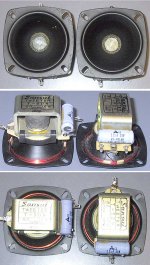
I am in the process of researching these old Sansui classics to look for tweaks to improve on the bass as much as physically possible (woofer has a smallish 6"cone surface). Other than the somewhat poor bass, these sound fine to me.
The speakers are bass reflex 2-ways with a horn tweeter, and I have learned that the crossover "circuit" between the nearly free-ranging woofer and tweeter is just a single 2.2uf cap.
I bring this up about the cap value because the one bit of info I could find anywhere on improving SP-50s, was an ancient thread where the user replaced the single 2.2uf cap with a 4.7uf cap - and noted "an improvement".
Nothing further mentioned in the thread about what was actually "improved" by increasing the cap value.
Could this bump in the "crossover" cap value tone down the free-ranging behavior of the woofer?
Thanks in advance as I have zero knowledge of the role of the cap in this simple crossover. In my experience, I understand that my KLH-32s have a lone 4.4uf cap as the crossover, and my EPI-100s have a lone 10uf cap as the crossover, meanwhile OTOH; my tiny Best Buy Insignia bass reflex 2-ways have at least 2 caps plus an inductor in the crossover circuit...
The speakers are bass reflex 2-ways with a horn tweeter, and I have learned that the crossover "circuit" between the nearly free-ranging woofer and tweeter is just a single 2.2uf cap.
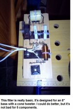
That is incorrect (at least in the half-dozen pairs i have had thru). If you look more closely you will see that the choke is wound arround the horn just under the bezel.
I haven't measured the inductor, but this is the XO drawing i have(i may have one of these kicking around so the possibility exists that i can measure it -- if i do i need to check whether any of the inductor is actually in series):
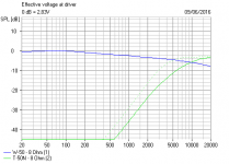
The impedance curve might be useful… top without XO, bottom with comparison, dotted is with XO.
The cap change is likely to push the XO frequency down to low. I would sub in a poly for the elco and leave it at that unless you can measure changes.
dave
Attachments
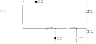
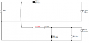
To raise the bass level, you add a 1mH coil. Now the midrange is 2-3dB lower. So you must attenuate the tweeter.
The below circuit allows for a polypropylene capacitor which is slightly brighter than a NP electrolytic.
7W wirewounds or ceramics resistor will do.
The 4.7uF would increase energy at crossover, which is about 3-4kHz with an 8" bass. If there is a hole there, it is common enough to use a 3.3uF in this position, but a horn tweeter should be quite bright there anyway.
Attachments

Thanks guys for the replies - and the pics as I have not had a chance to remove the back of one of these yet; I was going by what I read in the old thread about a single 2.2uf cap comprising the crossover circuit.
So if I understand your "measured XO" diagram, there are actually 2 inductors encircling the base of the tweeter horn?
As I understand it, inductors supposedly rarely "go bad", so the original thread about an increased capacitor value from the 2.2uf was a correct direction?
So if I understand your "measured XO" diagram, there are actually 2 inductors encircling the base of the tweeter horn?
As I understand it, inductors supposedly rarely "go bad", so the original thread about an increased capacitor value from the 2.2uf was a correct direction?
Increasing the 2.2uF capacitor is the correct direction for increased brightness in the treble between 3-10kHz. 4.7uF is overdoing it IMO. 3.3uF might be better.
But YOU want more perceived bass. Thus the modded circuit below is correct. You can, of course, change the 2.2uF also.
But YOU want more perceived bass. Thus the modded circuit below is correct. You can, of course, change the 2.2uF also.
Attachments
Thanks Steve and Dave!
Didn't mean to take so long to reply, as I appreciate your advice.
Now to wrap my head around what you have suggested in your circuit drawing Steve;
I need to add a 1mH inductor on the positive leg to the woofer, but this sits after the 2.2uF tweeter cap is first tapped off of the positive lead going to the W50 woofer.
I take it that this inductor reigns in the full-ranging woofer a bit?
Then, I add a 2.2ohm resistor on the positive lead to the T50N tweeter - but wired in series after the 2.2uF tweeter cap to the T50N tweeter?
Then; I add a “bridge” after the above 2.2ohm resistor; on which I bridge the positive and negative leads to the tweeter using a 15ohm resistor?
Finally from your circuit drawing, I am unsure what purpose the 3.3mH inductor is serving, which is shown bridging the positive and negative leads to the tweeter together between the 2.2uF cap and 2.2ohm resistor ?
Is this 3.3mH inductor needed?
Please advise if I have interpreted your information correctly, thanks!!
Read better : it is 0.3 mH ( or 300 uH )Is this 3.3mH inductor needed?
...which is the same as yours ( I've never seen such arrangement of rolling the coil around the basket...! ).
The two resistors together they make an attenuator
So you lose some deciBels
The crossover is formed by the two paths, one for the wf and one for the tw and they are indipendent ( as the coil in series for the woofer stops the high frequencies and the series cap for the tw stops the low frequencies).
If you fell uncomfortable with fixed attenuators you can buy an L-pad for 8 Ω speakers, so you can vary the decrease in gain continuosly ( many speakers used to have L-pads on the front or on the back for regulating brightness and presence )
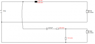
This circuit below will be very easy to implement and does much the same thing. 3W wirewound resistors will probably do, 7W for preference.
We are using the existing tweeter cap and coil remember. Just adding a 1mH coil to the bass, and a bit of attenuation to tweeter level with two resistors. You can try a 3.3uF instead of the 2.2uF if you want more at 3-7kHz.
You'll have to figure out what the three tweeter tags do in wiring this up. The coil must go across the two input terminals of the tweeter. That is where you add the 22R. The 2.2R goes in the live path in front of the 2.2uF capacitor. Simple job of soldering.
Attachments
Last edited:
- Status
- Not open for further replies.
- Home
- Loudspeakers
- Multi-Way
- Question please on a capacitor tweak in Sansui SP-50