On my garage Quicksilvers I measured the voltage on pin 3 at about 475 and pin 4 at 475. I was under the impression that it was supposed to be 43% on pin 4. Am I just not understanding this correctly or is there a problem with them? Its a converted 8417 running KT88's.
Attachments
The 43% for UL taps refers to the screen tap being at 43% of each side of the primary winding from the center, or B+, point. If you think of each half of the primary winding as 100% from the center (B+) point to the plate connection, the screen connection is 43% of the way to the plate connection. The is makes for a voltage differential between the plate and the screen in AC terms. For DC, all that counts is the DC resistance of half of the primary and there is a little less resistance from the screen tap to B+ than to the plate connection. Usually, the screen is just a little bit higher in DC voltage than the plate but it sounds like your transformer has a fairly low impedance primary and/or is wound with fairly large wire. This could give the same voltage reading on both pins. Hope this helps.
Ken
Ken
What he said. UL is hard on screens and it is common to have a 1k resistor between the screen and the 43% tap, to drop the voltage a little. It also helps to suppress parasitics if soldered ver close to the screen pin.
Can I have a diagram with voltages?
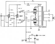
Is this what you mean ? The red line is the 475 volts dc you measure on plate and on screen. The blue is the total voltage on the plate, consisting of 475 dc plus 100 peak volts ac. The orange is the total voltage on the screen consisting of 475 dc plus 43 peak volts ac. 43 is 43% of 100.
reposted, diagram didnt show up
Attachments
The purpose of the resistors in series with the screens is mostly to reduce the screen dissapation when the tube is driven hard. If you exceed the screen's dissapation, it will die a rather quick death.
Same resistor is used if you strap the tube for triode.
The newer import tubes do NOT stand up as well as NOS USA and Euro mfr'd tubes in terms of slamming the screens at or over their nominal ratings. In other words they fry quick.
In an amp where the manufacturer runs the B+ on the high side or in excess of the suggested max B+ ratings in the tube books, the problem is worse. They seem to want to do this as it gives them a "higher" output power rating - nevermind that the difference between 35 and 40 watts (for example) or 60 and 70 watts is inaudible in practice. The tubes fry faster, which is good for the tube biz??
So, you can set the screen series resistors so that the screens do not glow white hot when the amp is driven to full power (on some tubes you can get a look at the screens, others you can't), but you'll find that at that point (magically) the tube produces (surprise!) just about excactly what the tube manual says it should, not the "extra" power the manufacturer says that the amp does.
This problem seems to be common in the USA made tube amps coming out of California (without mentioning brand names...). 😀
As always, these are merely my opinions, ymmv.
_-_-bear
The original form of UL had the screens feed from a seperate winding on the output transformer. It was isolated from the primary and was wound to provide 43% of the AC drive in the primary. Also, the DC screen voltage fed through it was set to a maximum of 43% of the plate voltage. Most tubes prefer a lower screen voltage than the plate voltage. This arrangement allowed many more options in output tubes, like transmitter tubes. Tubes for UL service are designed to handel the same voltage on screen and plate. This allows a cheaper transformer for UL service.
The purpose of the resistors in series with the screens is mostly to reduce the screen dissapation when the tube is driven hard. If you exceed the screen's dissapation, it will die a rather quick death.
So the manufacturer whom I won't mention omitted the screen resistors to save less than a buck? I will take your advice and add the screen resistors to both mono block amps.
Thanks for the diagram. It makes things clearer.
Hey, burnedfingers! 😀
Well, it is more likely that they cared mostly about the higher apparent output power that they can measure without the screens being current limited. Marketing, not the saving of the dollar or less in resistors.
I mean, seriously, if you (being a consumer) are presented with two very similar amps using the same tubes, which one would you buy? The one with the higher power or the one with the longer tube life and lower power (and maybe lower max distortion... maybe)??
And TUBESMAN, no matter what, if you exceed the screen's power/current rating the tube life will be shortened - sometimes to instantly short. 😱
_-_-bear
PS. as an experiment you can insert a resistor of suitably lower than the value needed to limit the screen current below max, and pop a 'scope across it (make sure ur scope is floating please... mine is sitting on an iso tranny for this purpose) and actually measure the screen current dynamically to see what the screen current looks like...
Absolutely, no one ever said you can exceed the design max ratings in ANY configuration. I was merely pointing out that the original design of UL would have placed 43% of B+ on the screen via a separate winding and separate supply. That type of transformer is still available but not cheap.
bear said:PS. as an experiment you can insert a resistor of suitably lower than the value needed to limit the screen current below max, and pop a 'scope across it (make sure ur scope is floating please... mine is sitting on an iso tranny for this purpose) and actually measure the screen current dynamically to see what the screen current looks like...
DO NOT DO THAT
The entire scope will be riding on high voltage. That includes the exposed part of the BNC connectors and even the entire face plate of the scope if it happens to be metal. Besides being extremely dangerous there are at least two reasons why you wouldn't get a good trace anyway.
The right way is easy with a dual trace scope (who doesn't have one of those?)
1 - Put both channels in AC mode.
2 - Attach one probe on each side of the resistor.
3 - Adjust both channels to the same sensitivity (volts/division.)
4 - Set one channel to invert.
5 - Set the scope to add the two channels.
Adding the channels with one inverted is the same as subtracting one channel from the other; you get the difference in voltage. That's the voltage drop across the resistor. Use Ohm's law to convert to current.
Keep your scope properly grounded. It'll work better and your family won't have the burden of burying your lifeless body.
-- Dave
- Status
- Not open for further replies.
- Home
- Amplifiers
- Tubes / Valves
- Question on voltages