Say, you have a power transformer that supplies 6.3VAC to tube heaters. Now you want to rectify the 6.3VAC heater supply from AC to DC, to reduce possible hums. So you add a full-wave bridge rectifier (4 silicon diodes, for example) after the 6.3VAC output from the power transformer. The question is - how much the DC after rectification will be, is it going to be higher than 6.3VDC or lower?
I hope it's higher than 6.3VDC so that we can add some CRC filter after the full-wave bridge rectifier and can still obtain some smoothed DC at 6.3V.
But if it's lower than 6.3VDC, then we can't obtain smoothed 6.3VDC anymore. 🙁
I hope it's higher than 6.3VDC so that we can add some CRC filter after the full-wave bridge rectifier and can still obtain some smoothed DC at 6.3V.
But if it's lower than 6.3VDC, then we can't obtain smoothed 6.3VDC anymore. 🙁
The answer is not as simple as it appears at first blush.
With rectifier circuit The DC output is given into a capacitor in short high-current pulses. so the voltage drop of the diodes depends on the current value at the peaks, and the transformer resistances will drop the peak voltage, too.
The easy way if to model it. The Duncan PSUD2 software makes it easy, even if you are unfamiliar with SPICE.
Practical solution:
If you are just trying to heat of few low-current indirectly-heated valves, try a half-wave rectifier. Just a single 5A schottky diode, and a 4700µF cap. You should get somewhere near to 8V, which is enough to allow RC filter, or just an R-dropper.
Don't oversize the cap, or the rectifier & trafo may get hot, due to increased peak currents. A ripple voltage even of 1V or more probably does not matter for IDHTs; but you can add the RC filter, should it prove necessary.
I build many many high gain guitar amplifiers which are run into 100db efficient speakers and have never had a problem with AC heaters causing hum. Make sure you are not over 6.3VAC (I aim for 6.1VAC to 6.3VAC) and elevate them to +40VDC via a simple L pad from the PS.
6.3V
You should have a volt or so excess to drop across a series filter resistor, but it depends on your line voltage,
and transformer. Use at least 2200uF for each capacitor, start with around 3.3R for the resistor,
and adjust its value for 6.3VDC output under the expected load. The series resistor drops the ripple voltage
as well as the DC voltage, so use a higher power rating part than for just the DC drop. If the voltage ripple
just after the rectifier is over 10%, increase the value of the first capacitor.
I hope it's higher than 6.3VDC so that we can add some CRC filter after the full-wave bridge
rectifier and can still obtain some smoothed DC at 6.3V. But if it's lower than 6.3VDC, then
we can't obtain smoothed 6.3VDC anymore. 🙁
You should have a volt or so excess to drop across a series filter resistor, but it depends on your line voltage,
and transformer. Use at least 2200uF for each capacitor, start with around 3.3R for the resistor,
and adjust its value for 6.3VDC output under the expected load. The series resistor drops the ripple voltage
as well as the DC voltage, so use a higher power rating part than for just the DC drop. If the voltage ripple
just after the rectifier is over 10%, increase the value of the first capacitor.
Last edited:
Thanks all for the reply.
I've never had any experience using the aforementioned modelling/simulation software, so it would be kinda difficult for me to get the result, besides, I have no idea about the specs of the power transformer - not bought yet. So just a general question.
I'm just interested in finding out what the DC voltage would look like after the AC has been rectified by a 4-diode silicon full-wave bridge rectifier?
If the AC coming out of the transformer secondary winding is 6.3VAC (as lots of popular transformers supply 6.3VAC for tube heaters), is the DC coming out of the full-wave rectifier going to be higher or lower than 6.3V?
Or both possible, if this is the case, how to ensure that we can get some rectified DC higher than 6.3VDC, coz obviously we want to add some CRC or CLC filter to smooth the rectified DC. And there will be some voltage drop from the CRC/CLC filter, but we want to get 6.3V rectified & smoothed DC for tube heaters.
You don’t need exact specs. Put in 6.3 volts, pick a bridge rectifier, add a capacitor, press button. Done.
But I have no idea what the rectified DC will be after the full-wave rectifier, if 6.3VAC goes in and 5.0VDC comes out, then I will never get 6.3VDC.😕
There's this thing called Ohm's Law which says that current, voltage and resistance all exist in a balanced relationship.
For a given resistance (like the DC resistance of a power transformer secondary winding):
- For the same resistance, increase the current through that resistance and more voltage will be dropped across that resistance.
- For the same current, increase the resistance and more voltage will be dropped across that increased resistance.
If a tube's heater draws 0.6A (600mA) of current (at 6.3V applied to that heater):
- If the DC resistance of the transformer secondary is 1 ohm, a whopping 0.6V will be dropped across that DC resistance.
- If the DC resistance of the transformer secondary is reduced to 0.5 ohm, then the voltage dropped across the transformer secondary will be reduced to 0.3V.
What does that tell you? It tells you that you need to measure the DC resistance of the transformer secondary to be able to predict what DC voltage you might get out of it when rectified and loaded by tube heaters.
In other words, it's a bit complicated. Real world stuff has flaws, characteristics, variances, all that good stuff.
--
But I have no idea what the rectified DC will be after the full-wave rectifier, if 6.3VAC goes in and 5.0VDC comes out, then I will never get 6.3VDC.😕
then do not rectify, use the cathode bias dc voltage to bias the ac filaments to mitigate hum and noise...
as a general rule no element inside of a tube is to be leaft hanging unconnected to anything, the filaments needed to have a dc bias or else connected to ground, either thru a center tap, or a false center tap or thru capacitors even...
Thanks, I understand the Ohm's Law pretty well, and I see your point.
Let's say, the voltage drop across the transformer 6.3VAC secondary winding can be ignored, assuming the resistance there is small enough. What the output DC will be, if we feed 6.3VAC from the transformer secondary winding into the 4 silicon diode full-wave rectifier?
Let's say, the voltage drop across the transformer 6.3VAC secondary winding can be ignored, assuming the resistance there is small enough. What the output DC will be, if we feed 6.3VAC from the transformer secondary winding into the 4 silicon diode full-wave rectifier?
This question has been asked before. Many times before.
6.3VAC heaters to filtered/regulated 6.3VDC. best solution? | GroupDIY
The Valve Wizard
Tube DIY Asylum
6.3vdc form 6.3v ac PSU
I'm sure there are more out there...
6.3VAC heaters to filtered/regulated 6.3VDC. best solution? | GroupDIY
The Valve Wizard
Tube DIY Asylum
6.3vdc form 6.3v ac PSU
I'm sure there are more out there...
then do not rectify, use the cathode bias dc voltage to bias the ac filaments to mitigate hum and noise...
as a general rule no element inside of a tube is to be leaft hanging unconnected to anything, the filaments needed to have a dc bias or else connected to ground, either thru a center tap, or a false center tap or thru capacitors even...
Elevating tube heater, virtual center tap...these are all good tips to get rid of hums. Thanks.
But I'm still interested in getting rectified & smoothed DC for tube heaters.🙂
This question has been asked before. Many times before.
6.3VAC heaters to filtered/regulated 6.3VDC. best solution? | GroupDIY
The Valve Wizard
Tube DIY Asylum
6.3vdc form 6.3v ac PSU
I'm sure there are more out there...
That's great, I will have a look at them. Thanks a lot!🙂
a bridge represented a 1.5 vdc loss...so depending in the size of that traffo and the dc resistances, ymmv...
I rectified 6,3v in my P-P kt77 amp for the driverstages.
I had to use a LDO regulator to get 6,3v out.
I had to use a LDO regulator to get 6,3v out.
DIYish, what dc heater voltage you will end up with depends a lot on what you have there. Aspects that can change the resulting heater DCV are mains voltage, mains voltage distortion (especially flat topping), the transformer and its loading, the diode type you use, the rectifier configuration used (eg. full bridge, or full wave if the heater has a CT), the level of filter capacitance, the DC heater loading.
You have obviously seen posts and commercial schematics showing 6.3Vdc heater off a 6.3Vac winding, so it is all up to your particular situation - there is no 'copy and paste' path to take here that will give you an answer to 0.1V. Start by wiring up a circuit with the diodes you have available, and the valve heater loading you want to use, and see what you get. You may then only have two options to tweak the DCV - diode type and filter capacitance value.
Some test results and discussion in section 8.2 of linked doc:
https://dalmura.com.au/static/Power%20supply%20issues%20for%20tube%20amps.pdf
keep in mind also the primary voltage situations from where you are, a 110v primary traffo will have higher secondary voltage on a 120 volt line and lower at 100 volt line, situational awareness really helps...
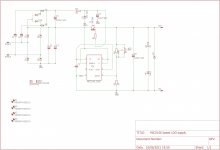
MIC5156 family of Mosfet LDO controllers should enable someone to build a practical 6.3VAC to 6.3VDC converter. But the bottleneck is the required auxillary voltage.
Bellow the schematic of a board i have in the mail from JLC that should give 6.3VAC to DC at 2A from a high current winding.
Pass device would be RFP12N10L, which is the mosfet i currently use for my heater regulators.
Bellow the schematic of a board i have in the mail from JLC that should give 6.3VAC to DC at 2A from a high current winding.
Pass device would be RFP12N10L, which is the mosfet i currently use for my heater regulators.
Attachments
- Home
- Amplifiers
- Tubes / Valves
- Question on rectifying heater supply from AC to DC