Been working on various experiments with different kind of amplifiers and hybrids and whatnot and ive come to wonder how to use planes properly
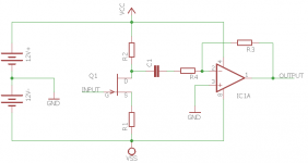
Ive included a rough simplified sketch of a example circuit. There is a class-A jfet amplifier and a inverting opamp. My question is how would i use planes on a 2-sided PCB with this?? With the jfet i would go for using a plane for the -12v, but for the opamp i would use the GND as a plane hence my dillema:
Do i:
- Choose either the GND or -12v for the entire pcb?
- Give both -12 and 12v planes and use traces for GND?
- Section the parts on the pcb with each part having it's own plane?
- Not use any planes at all?
- Just use whatever is convenient, it doesn't matter cause AF?
- Something else?
Attachments
Last edited:
Ive included a rough simplified sketch of a example circuit. There is a class-A jfet amplifier
and a inverting opamp. My question is how would i use planes on a 2-sided PCB with this?
It's best if you post the complete circuit, including how the input and output are connected.
There also must be decoupling capacitors.
Last edited:
The most important thing is the power rails.
Is it really two 12volt batteries or are you going to use a transformer, rectifier and smoothing caps ?
The charging impulses to the smoothing capacitors can really upset the audio ground.
The input (rectified ac and zero volt line) to the smoothing capacitors should come from rectifier and the other side should go out to audio circuit.
I got caught out with a mixer with that, just laid it out any old way and got 1VAC of hum on output with input shorted !
It's best if you post the complete circuit, including how the input and output are connected.
There also must be decoupling capacitors.
It's really is mostly like the example. A simple class-a input amplifier stage with possibly high impedances and a opamp handling line output. Yes there is naturally decoupling between the stages and the input/output.
Just want to know what i should consider in general. How i should use planes and whatnot in audio where you got different parts that use a different reference. not looking for a circuit specific solution, Just looking for overall information so i can learn. 🙂
In general, I've used ground planes only and have heard from other engineers that that is the way to go.
The following site has good layout and EMC guidelines: Clemson Vehicular Electronics Laboratory: Electromagnetic Compatibility / Electromagnetic Interference
The following site has good layout and EMC guidelines: Clemson Vehicular Electronics Laboratory: Electromagnetic Compatibility / Electromagnetic Interference
I usually connect my copper pours to the zero volt line.
That doesn't catch everything though, you might still need to star ground certain parts of the circuit. Especially the power supply.
That doesn't catch everything though, you might still need to star ground certain parts of the circuit. Especially the power supply.
I own a book on EMC as part of electrical engineering study so i know how to be carefull on layout and avoid putting sensitive stuff near the power-supply and such. I'm just sadly missing on info in regards of combinations of planes (pure ground or gnd+supply and so on) in circuits in the AF terittory.
That is the specific info i'm looking for. Is there a preference? should i section the planes (so GND pour around the opamp,-12 around the jeft)? just use a GND pour? Only use pours on the area where it's usefull (so no pour around the JFet). That kind of info.
Thanks for the help so far 🙂
That is the specific info i'm looking for. Is there a preference? should i section the planes (so GND pour around the opamp,-12 around the jeft)? just use a GND pour? Only use pours on the area where it's usefull (so no pour around the JFet). That kind of info.
Thanks for the help so far 🙂
Last edited:
I put copper pours connected to zero volts around all the audio.
I don't put copper pours around the power supply so I don't get smoothing capacitor charging impulses modulating the ground pour.
This is quite a simple circuit so my comments should work well.
I have just finished a valve pcb with copper pours.
This is a bit more complicated as it has valves, high volts and high impedance circuits and transformers on the pcb.
should i section the planes (so GND pour around the opamp,-12 around the jeft)? just use a GND pour?
Only use pours on the area where it's usefull (so no pour around the JFet).
Much of the function of power and ground planes is to allow bypass capacitors to function as well as possible,
without increasing component lead inductance. Also, ground planes allow image currents to return directly under
the signal lines, minimizing circuit loop areas.
Last edited:
- Status
- Not open for further replies.
- Home
- Design & Build
- Construction Tips
- Question on PCB planes.