There is a fair amount of useful discussion in the archives about appropriate T/S parameters for dipole woofers, but I couldn't find so much about mids or mid woofers. Does it not matter so much, because you simply cross the woofer higher with a higher Qt mid woofer?
Related question: it doesn't seem from first glance the most of the available speaker modeling software addresses dipole response. Any recommendations?
Sheldon
Related question: it doesn't seem from first glance the most of the available speaker modeling software addresses dipole response. Any recommendations?
Sheldon
It does matter but not a great deal.
A second order high pass can be easily used to compensate
for the frequency response due to to the units Q.
At frenquencies above the baffle width wavelength the mids
response on the forward axis is independant of loading, i.e.
its the same in a box and on a baffle.
At lower frequencies response is heavily influenced by
the room and the position of the dipole in the room.
Anechoic response is modeled by a 6dB/octave rolloff.
🙂 /sreten.
Thanks,
It would be interesting to have a program to play with response, depending on baffle dimensions and speaker placement on the baffle. I would think that it would not be that hard to model. Or is it easy enough to experiment, so not worth the effort to develop the model? That seems one nice thing about using conventional drivers on an open baffle. Real easy to make a small baffle, then just extend it in various dimensions to evaluate response.
Sheldon
That seems one nice thing about using conventional drivers on an open baffle. Real easy to make a small baffle, then just extend it in various dimensions to evaluate response.
In a word, YES! 😉 Just have loads of different sized pieces of wood/MDF/plywood handy and you can change the baffle size/shape in a jiffy. Then sit back and listen for a couple of days before repeating the process.
Konnichiwa,
Hmmm. Yes and no. The Q (Qts/Qms/Qes) determine the behaviour of the driver around it's resonance point.
If you are using (for arguments sake) a 5.25" Driver with a Qt of 0.3 and an Fs of 50Hz with a 500Hz X-Over on an open baffle the result will be fine, as by the time you reach 500Hz the drivers efficiency has reached the maximum.
If for arguments sake you where to use the same driver with a 100Hz X-Over you would have to equalise the driver heavily as there would be a substantial loss even at the X-Over frequency.
Well, I have written something LIKE that, though it is as of yet somewhat inaccurate (good enough in practice for basic feasibility studies though).
http://www.exdreamnet.de/download/Xlbaffle.xls
It is an Excel Spreadsheet that runs under Microsoft Excel 2000 (probably also 97/XP but not tested) but NOT under any other Office Software like Star Office.
The baffle assumes ideal assymetric placement of the driver on the baffle (meaning making the distance to each and every edge non-divisible by any other) and takes account of room re-inforcement (inaccurate but close enough until I have time for a re-write) but not of room modes.
Sayonara
Sheldon said:There is a fair amount of useful discussion in the archives about appropriate T/S parameters for dipole woofers, but I couldn't find so much about mids or mid woofers. Does it not matter so much, because you simply cross the woofer higher with a higher Qt mid woofer?
Hmmm. Yes and no. The Q (Qts/Qms/Qes) determine the behaviour of the driver around it's resonance point.
If you are using (for arguments sake) a 5.25" Driver with a Qt of 0.3 and an Fs of 50Hz with a 500Hz X-Over on an open baffle the result will be fine, as by the time you reach 500Hz the drivers efficiency has reached the maximum.
If for arguments sake you where to use the same driver with a 100Hz X-Over you would have to equalise the driver heavily as there would be a substantial loss even at the X-Over frequency.
Sheldon said:Related question: it doesn't seem from first glance the most of the available speaker modeling software addresses dipole response. Any recommendations?
Sheldon said:It would be interesting to have a program to play with response, depending on baffle dimensions and speaker placement on the baffle. I would think that it would not be that hard to model. Or is it easy enough to experiment, so not worth the effort to develop the model? That seems one nice thing about using conventional drivers on an open baffle. Real easy to make a small baffle, then just extend it in various dimensions to evaluate response.
Well, I have written something LIKE that, though it is as of yet somewhat inaccurate (good enough in practice for basic feasibility studies though).
http://www.exdreamnet.de/download/Xlbaffle.xls
It is an Excel Spreadsheet that runs under Microsoft Excel 2000 (probably also 97/XP but not tested) but NOT under any other Office Software like Star Office.
The baffle assumes ideal assymetric placement of the driver on the baffle (meaning making the distance to each and every edge non-divisible by any other) and takes account of room re-inforcement (inaccurate but close enough until I have time for a re-write) but not of room modes.
Sayonara
Thanks, makes sense. Goes with the impression one gets from looking at the freq response curves drivers that differ in Qt (that is, if such things are measured under similar conditions, which they don't often seem to be).
I did try to download the spread sheet yesterday, but the link on the thunderstone site didn't work. This one does, Thanks.
Sheldon
I did try to download the spread sheet yesterday, but the link on the thunderstone site didn't work. This one does, Thanks.
Sheldon
It is an Excel Spreadsheet that runs under Microsoft Excel 2000 (probably also 97/XP but not tested) but NOT under any other Office Software like Star Office.
Why not Star Office? Some of usreally hate using MicroShaft anything. WinDoze is bad enough, without making things worse by installing Office.
Working on changing that feature.
Jocko
sfdoddsy said:
Thanks, let me take the opportunity to ask a related question:
On the dipole woofer side, some installations use a w type frame with the woofers facing and the box openings facing the listener. This obviously shouldn't affect Lf sound, but what is the upper cuttoff where internal reflections begin to become audible?
Sheldon
Konnichiwa,
Where I work we use Mickeysoft so I use iut too. I'm not at all fussed. StarOffice is as bad bloat and bugware as MS Office and I get both for free. MS tends to work more reliable and has more features I actually need.
Just being pragmatic, no axe to grind....
Sayonara
Jocko Homo said:Why not Star Office?
Where I work we use Mickeysoft so I use iut too. I'm not at all fussed. StarOffice is as bad bloat and bugware as MS Office and I get both for free. MS tends to work more reliable and has more features I actually need.
Just being pragmatic, no axe to grind....
Sayonara
Jocko Homo said:
Why not Star Office? Some of usreally hate using MicroShaft anything. WinDoze is bad enough, without making things worse by installing Office.
Working on changing that feature.
Jocko
try red hat 9.0 + Open Office. it is fast, bug fre, and does not crash. we have moved 30 users to this platform with great success.
Sheldon said:On the dipole woofer side, some installations use a w type frame with the woofers facing and the box openings facing the listener. This obviously shouldn't affect Lf sound, but what is the upper cuttoff where internal reflections begin to become audible?
Sheldon
me 2. was wondering what advantage teh W frame has over a Std. dipole. the W frame is about 18-20" wide, 16" tall and 16" deep (approx).
2 12" woofers in vertical alignment and with sides instead of a 48" wide baffle would be 16" wide, 16" deep (baffle folded), and 28" tall. given that 34" is about listening height the dipole woofer can easily be accomodated below the full range speaker (or 2 or 3 way).
Maybe this is a way to determine ringing.....
If you look at the linkwitz site, I believe the resonance is a standard distance caused by the parallel wall.
Resonance = (1129/4) / Distance in inchs
That would mean 1/4 wavelength.................
For example a h box with 12" by 12" has a resonance of 282 (linkwitz was near 263).
This might help for a guestimation...............
The advantage of the "W" construction is force cancellation because both cones are moving in opposite directions at all times. This eliminates the "rocking" force that is created with a conventional dipole setup. However, the cavities created by the more complicated structure create a peaked response that should probably be addressed with a notch filter if the electrical roll-off is too shallow.
If a 4th-order electrical crossover is used and the xover point is not much above 100 Hz it should work okay, but a more refined design would still include a notch filter.
Cheers,
Davey.
If a 4th-order electrical crossover is used and the xover point is not much above 100 Hz it should work okay, but a more refined design would still include a notch filter.
Cheers,
Davey.
what about the H construction where one woofer is mounted facing forward and teh other facing backward
There is no force cancellation with the "H" construction because both cones are moving the same direction, but you still get even-order distortion reduction if one driver is inverted.
There will still be a peak in response associated with the quarter-wavelength distance created by the box construction.
You can make a calculation of the frequency, but it's best to measure it with an upclose microphone.
Cheers,
Davey.
There will still be a peak in response associated with the quarter-wavelength distance created by the box construction.
You can make a calculation of the frequency, but it's best to measure it with an upclose microphone.
Cheers,
Davey.
reason i am asking...i intend to convert my present sealed box subs (2 x 12" in 30"Wx18"H x 22"D) into dipole. i find on some music there is a distracting boom with the present subs. alternately i would look at a electrical ckt to vary the Q.
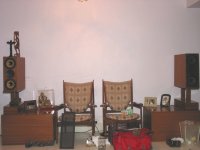
the present subs are built so that i can use teh ast sitting on the sub if the sub is vertical and use the home made 12" stands if the sub is horizontal like in the photo.
the present subs are built so that i can use teh ast sitting on the sub if the sub is vertical and use the home made 12" stands if the sub is horizontal like in the photo.
Attachments
Re: Maybe this is a way to determine ringing.....
Right you are. Looking at the site he covers this specifically. Great site, but you really have to travel around it a few times to figure out where everything is.
Interesting point about the force cancellation. I'd missed that one, but it's obvious in retrospect.
Okay, so the resonance can be dealt with, as can box movement. Still, apart from resonance, I'm curious as to what the w format does to the directional response of the midrange frequencies that interact with the box dimensions. Or is it just not significant?
Sheldon
norman bates said:If you look at the linkwitz site, I believe the resonance is a standard distance caused by the parallel wall.
Resonance = (1129/4) / Distance in inchs
That would mean 1/4 wavelength.................
For example a h box with 12" by 12" has a resonance of 282 (linkwitz was near 263).
This might help for a guestimation...............
Right you are. Looking at the site he covers this specifically. Great site, but you really have to travel around it a few times to figure out where everything is.
Davey said:The advantage of the "W" construction is force cancellation because both cones are moving in opposite directions at all times. This eliminates the "rocking" force that is created with a conventional dipole setup. However, the cavities created by the more complicated structure create a peaked response that should probably be addressed with a notch filter if the electrical roll-off is too shallow.
If a 4th-order electrical crossover is used and the xover point is not much above 100 Hz it should work okay, but a more refined design would still include a notch filter.
Cheers,
Davey.
Interesting point about the force cancellation. I'd missed that one, but it's obvious in retrospect.
Okay, so the resonance can be dealt with, as can box movement. Still, apart from resonance, I'm curious as to what the w format does to the directional response of the midrange frequencies that interact with the box dimensions. Or is it just not significant?
Sheldon
Sheldon,
It's really not that significant because those frequencies will be well attenuated by the crossover slope and notch filter since they're above the normal operating range.
The woofers in their passband exhibit a figure-eight response that becomes more directional as frequency increases. In some cases you may have to toe-in the woofers to better aim them at your listening position so they make a better transition to the midrange speakers.
The "W" enclosure makes for a more compact setup (height-wise) than the "H" baffle and will probably have a better SAF.
Cheers,
Davey.
- Status
- Not open for further replies.
- Home
- Loudspeakers
- Multi-Way
- Question on mids for all you Dipole guys