I have been building Tube amps for awhile and decided to learn about SS.
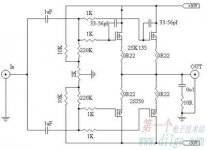
I've found this simple design on the web and have a question about the bias for the Mosfet.
Looking at the 2SK135:
The Voltage is +50v on the Drain:
A 10K and 1K Resistor create Voltage divider resistor to create the Bias Voltage of 4.54v to the Gate.
By viewing the operating characteristic graph of the 2SK135,with the operating point of 4.54v on the Gate and 50v on the Drain will put it pass its power limits ? Or am I missing something ? I assuming no significant Gate Current.
Please correct me if I'm wrong on my other thoughts and guesses on the circuit:
1. The additional Caps on only the 2SK135 is to balance the capacitance of the 2SJ50
2. There is no need for protection diode since it build in to the Mosfet
Thanks in Advance
Attachments
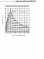
If I understand you correctly then you are reading the Vgs vs Id properly.
50Vds and 4.54Vgs is way outside the the 25degC SOA.
But you must take account of the voltage drop across Rs=0r22 and use this to correct the Vgs to the Vbias applied by that 10k:1k resistor ladder.
Assume as a first guess the voltage dropped across Rs is 1V
Then Vgs = Vbias - Vdrop gives Vgs= 3.54V Still way outside the SOA.
Better to start at the other end.
Pick a bias current you want, say 150mA. Vdrop = 0.22*0.15 ~33mV
Assume 50Vds @ this quiescent current.
Look up the graph and find the typical Vgs required to pass this bias current. I'd guess from the graph ~0.8Vgs gives that bias current.
Add those two voltages 33+800 to give 833mV of bias from the resistor ladder.
But, a big warning, FETs are notorious for having an enormous spread in parameter values. The bias voltage will need to be found for every (individual of the same type) FET you put in the circuit.
- Status
- Not open for further replies.