Eh, edit time over. The VituixCAD diffraction simulator has zero thickness to the baffle and is simplified in many ways, so what comes around from the other side perfectly coincides with the diffraction backwave that emits, hence both OB and closed box diffraction sims look pretty much the same. If baffle was very thick, the sound coming from the backside would have more delay than the back wave at the front edge, and they would not coincide and reinforce each other as perfectly.
So, the dipole peak and dip is a concept that exists separately to the diffraction backwave just like Linkwitz writes and calculates, but observed from listening window it is about the same as diffraction back wave as long as one driver is used for both front and back sound and the baffle is much less thick than wide, in other words an OB.
So, the dipole peak and dip is a concept that exists separately to the diffraction backwave just like Linkwitz writes and calculates, but observed from listening window it is about the same as diffraction back wave as long as one driver is used for both front and back sound and the baffle is much less thick than wide, in other words an OB.
Another simulator view to this, VituixCAD is nice as it's real time and simplified in a away that it enables do this kind of "in isolation" tests.
Here is the same 40cm baffle and ~6" ideal driver I've used on previous examples. It's a closed box to have only the baffle edge effect.

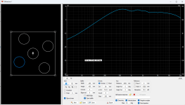
Export full polars to the main program, flip around 180deg and flip polarity we get the sound that would come around with a OB speaker from back side towards the listening window. So this is basically backside response of the OB speaker towards 0-axis in isolation, without sound from the frontside.

Here is the front side of OB in isolation, without effects of the backside:

These two combined makes the OB speaker response towards 0-axis. Familiar looking graph? Just the diffraction simmed OB from previous post next to it


What we can do now is increase baffle thickness, try to separate sound from backside making the "dipole peak and dip" from diffraction back wave peak and dip of the frontside 😉


Fun stuff 🙂
Here is the same 40cm baffle and ~6" ideal driver I've used on previous examples. It's a closed box to have only the baffle edge effect.
Export full polars to the main program, flip around 180deg and flip polarity we get the sound that would come around with a OB speaker from back side towards the listening window. So this is basically backside response of the OB speaker towards 0-axis in isolation, without sound from the frontside.
Here is the front side of OB in isolation, without effects of the backside:
These two combined makes the OB speaker response towards 0-axis. Familiar looking graph? Just the diffraction simmed OB from previous post next to it
What we can do now is increase baffle thickness, try to separate sound from backside making the "dipole peak and dip" from diffraction back wave peak and dip of the frontside 😉
Fun stuff 🙂
Basically, if distance from back source to (front) edge is different to front source to front edge, and they do not have same frequency response either, two things happen:
first "the dipole peak and null" aren't as pronounced as in ideal case as both interfering sounds are less coherent compared to ideal flat OB. Second the front diffraction back wave does not align as ideally with the sound coming from back, like with the diffraction tool ideal transducers on thin baffle. Both of these blends the combined effect of ideal OB diffraction to something more mellow, hence no serious diffraction peak and dip like in simulation with perfect match.
In your MEH, there is relatively big obstruction on the backside: the waveguide and all the drivers has more bulk than a single woofer basket and magnet would, certainly more than a ideal flat disk. Then on the front there is acoustic low pass filter due to the apertures adding delay and changing frequency response. The apertures also increase distance from the front sources to edges. All of these make front and back sound differ a lot, and makes both "dipole peak" and front edge diffraction back wave differ, mellowing out all the interference you see on the measurements. So, "dipole peak and dip" isn't as strong as it could, and further randomized by front edge diffraction back wave not aligning with it either.
It's another thing if this is audible or not, you could think there is lots of sound delayed and EQ:d sound radiating from the edge towards listening window with some delay behind direct sound, possibly having some perceptual effects. On the other hand the edge is relatively close so that the secondary sound comes in about 1ms after direct sound integrating with the direct sound and all you'd hear is the wiggle in the frequency response.
Last edited:
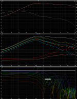
Just for info - this is in room measurement of my open backed 9 sided horn - including the reflections, microphone is ca 1 meter from the mouth (I know, too close). I think the first three dips (ca 150 - 350 Hz) are caused by the room/environment, since they can be seen both in the midranges and LF drivers.

I forgot to say, I have not seen any prominent dipole peak and dip (will check more in detail later).
I forgot to say, I have not seen any prominent dipole peak and dip (will check more in detail later).
Last edited:

Is there audible "horn sound"? as per the reasoning above, with such hard edge at the mouth there is strong diffraction backwave back into the device, which reflects back out, then again and so on. More over, it's not just the diffraction back wave, but also the OB sound from backside diffracts into the horn and reflects out. This all kind of maximises "mouth reflection back to the throat" phenomenon, although as per the above reasoning perhaps it melows out some?
edit.
As yours is a horn all the way, compared to relatively flat baffle of Patric Bateman, the sound from inside would be much louder than sound from backside, perhaps the dipole pattern isn't nearly as strong, and backside sound doesn't reflect much inside the device or be loud enough to be audible. Actually full polars would be most interesting, perhaps the OB nature here just underlines the horn radiation pattern in a way, it's not much of a dipole I think.
Last edited:
Not realy, it just sound very similar to the square one - but that one had hard edges as well. However, I would like to add some temporary damping to that edge - like rolled towels or some sort of foam to see the effect.
Unfortunately not. I can do only very little in the room, it needs to be done outside when the temperatures will be more friendly.
Ok, big devices are tough to measure 🙂
Without measurements perhaps simplification would do? For easy math let's use the spatial loading concept. Inside the horn radiation environment for a driver could be something like eight space, while the outside is almost full space. Difference of the two would be 18db. If this was the case with an OB, where backside is -18db compared to front, it would have roughly monopole response. The back side sound has attenuation compared to front almost like there was a box. At least for the short wavelengths where the horn works as an obstacle. On long wavelength, perhaps the difference gets leveled.
If it is flat baffle like in opening post, both sides have roughly similar radiation space and there is some dipole kind of a pattern.
Last edited:
It would be really interesting to model this. Also the bandbass effect makes this difference even larger.
Indeed, trying to imagine I think what it ends up is kind of cardioidish thing more than a dipole 🤔
As the horn loses pattern control (for front sound) the front sound has kind of a high pass slope to it. On the other hand back sound remains about the same through out the bandwidth as there is hardly any loading (almost fullspace). Result is the frontal sound SPL reduces from huge boost on highs to no boost on lows, which means balance between front and back gets more similar the lower the frequency. This high pass effect changes delays between front and back as well. So, device like this isn't likely a dipole but just appears to have pattern control lower than it should? and has penalty for bass SPL like dipole / cardioid would.
As the horn loses pattern control (for front sound) the front sound has kind of a high pass slope to it. On the other hand back sound remains about the same through out the bandwidth as there is hardly any loading (almost fullspace). Result is the frontal sound SPL reduces from huge boost on highs to no boost on lows, which means balance between front and back gets more similar the lower the frequency. This high pass effect changes delays between front and back as well. So, device like this isn't likely a dipole but just appears to have pattern control lower than it should? and has penalty for bass SPL like dipole / cardioid would.
Last edited:
Adding a fifth driver makes a tremendous improvement.

This is the sim of a sixteen inch wide baffle with four woofers

this is the sim of a sixteen inch wide baffle with five woofers

this is the predicted polar response (normalized) of an open baffle with five woofers
This is the sim of a sixteen inch wide baffle with four woofers
this is the sim of a sixteen inch wide baffle with five woofers
this is the predicted polar response (normalized) of an open baffle with five woofers
Attachments

If you can live with an off-axis dip at 1khz, it looks like you could cross the 16" wide baffle as high as 1khz
But ideally it would be done somewhere around 400Hz or so, where the polars are better behaved
If there's a decent midrange that can handle high power, it might be tempting to reduce the baffle to around ten inches or so, or even less. I'm definitely seeing the appeal of small baffles, but multiple woofers DOES seem to improve things quite a bit.
I see, and a single 6" on a 15.7", basically driver's edge is 5" from the side of the box.
or front driver's edge is about 10" away from back driver's closest edge.
So 1129 / (10" /12" ) = dip at 1350hz..................
or diffraction closer to 5".......................
or front driver's edge is about 10" away from back driver's closest edge.
So 1129 / (10" /12" ) = dip at 1350hz..................
or diffraction closer to 5".......................
Yeah it's all relative, you can use more and bigger drivers, just use as small baffle as possible still fitting everything in. Idea of small baffle is that it's as small as possible to fit everything, but not bigger than that. Edge as close to transducer as possible. Any sized naked driver is smallest possible baffle and any roundover is good as long as it starts immediately beside the transducer.If you can live with an off-axis dip at 1khz, it looks like you could cross the 16" wide baffle as high as 1khz
But ideally it would be done somewhere around 400Hz or so, where the polars are better behaved
If there's a decent midrange that can handle high power, it might be tempting to reduce the baffle to around ten inches or so, or even less. I'm definitely seeing the appeal of small baffles, but multiple woofers DOES seem to improve things quite a bit.
Of course with a MEH there is high frequency transducer on the middle, which would also make secondary sound source on the edge for the bandwidth it radiates sound toward the edge, so it has quite a big baffle unless the whole thing is optimized waveguide. If you want to reduce effects of edge diffraction toward listening window you must start from the waveguide part for highs, which should have such a profile no problematic diffraction occurs within tweeters pass band. Next task is fit in the woofers you'd crossover to, which in a case of MEH asks for bigger waveguide overall, which then would diffract even lower frequencies and the waveguide profile would need to support low diffraction idea for the whole usable bandwidth, also house the woofers, so it's a complex situation to optimize. The woofer apertures would diffract some highs, and so on, so it's impossible to avoid diffraction effects completely, as everything is on same device. If tweeter and woofer were two different horns they could both be optimized separately, but when you'd bring them closer together to make complete system they'd now be in each others acoustic environment making reflections, wouldn't be a point source, and so on. Well, all we need to do is make important problems go away, not sure if chasing every bit of reflections and diffraction is necessary or productive 🙂
So, what's the most important lesson here? I think it is likely that the open backed woofers could keep DI high bit lower in frequency than the mouth size suggest, which in itself is a fine goal. Doing so while trying to mitigate some edge diffraction effects takes some extra effort. Open backed woofers would be nice, simplifies construction a lot.
Thinkin bit further with open back woofer idea: why not just use coaxial driver naked? 8" / 10" / 12" / 15" MEH done without any construction. One could also buy a coax woofer with detachable waveguide and replace with your own. Custom waveguide could close on the woofer edge, have some rollback for diffraction interference free highs, print some holes to it to have it a MEH. Use what ever profile ticks the boxes, mabat has recently shown a straight tube section on throat works fine so one can bring the tweeter as far out from the woofer as one wants, and start the waveguide profile there.
Last edited:
If the intention of using a dipole is avoiding a boxy sound then open back is the only way to go.
But something I always wanted to try is using two identical front mounted speakers (Faital 3FE for test purposes) via my Behringer DCX one delayed between 4 to 7 milliseconds. I would not be surprised if the effect perceived by our brain was identical to a dipole.
But something I always wanted to try is using two identical front mounted speakers (Faital 3FE for test purposes) via my Behringer DCX one delayed between 4 to 7 milliseconds. I would not be surprised if the effect perceived by our brain was identical to a dipole.
In a given room you have very little control over the back wave. The position for the best front wave result is seldom also the best position for the back wave. So we fiddle around till we find the best compromise.
On top of that the back wave is ragged and rolled off due to obstacles and surface texture of our walls.
In using a second front wave speaker unit we have control over the time and amplitude of it and the frequency response is nearly identical.
If one uses a computer as source he could route a second timedelayed and amplitude adjusted signal to the same output without doubling of speakers.
With my Behringer DCX I might try to send a time delayed and amplitude adjusted signal to the same amplifier. Who knows what can be achieved via this route.
Greetings Klaus
Last edited:
I think you will get different levels of comb filtering like that. IMHO the more chaotic and unpredictable the reflections are, the better. But comb filtering does not have to be a bad thing and you get it with a normal stereo speaker pair anyway and (again IMHO) the effect is lessened by random room reflections filling the gaps unless you have a beaming tweeter.
I would recommend to try the MDD speaker - nine tubes in front of a 3FE22 - the tubes delay the sound by their length and the back side is open as well. They have a really nice "room filling stereo almost everywhere effect", however limited in SPL by the single 3FE22.
I would recommend to try the MDD speaker - nine tubes in front of a 3FE22 - the tubes delay the sound by their length and the back side is open as well. They have a really nice "room filling stereo almost everywhere effect", however limited in SPL by the single 3FE22.
- Home
- Loudspeakers
- Multi-Way
- Question for the Dipole Experts