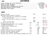
Refer to the tube manual, the 7N7 good up to 300vdc.
Actually, what is the recommended maximum operating voltage?
Actually, what is the recommended maximum operating voltage?
So it has no big deal between 250 and 300v for this tube type?
If a circuit build around with 6SN7, can I rewire the tube socket and replace with 6GU7??
If a circuit build around with 6SN7, can I rewire the tube socket and replace with 6GU7??
Since each triode section is sitting on top of another triode section(totem poll as some call it) they only see half the B+.
At 300 volt b+ each tube will only see 150 or so volts.
At 250 volt b+ each tube will see 125 or so volts.
Using the same bias resistors the 300 volt layout will run about 10% more current through the tube than the 250 volt layout.
Easily well under max voltage and current specs if that is your main concern.
Yup.
Obviously at 500 volt B+ the bias resistors would all have to be recalculated.
Check out John Broskie's Tubecad.com site.Tons of info on the very circuit your interested in.Stuff that's incredibly helpful if you want to learn more.
Obviously at 500 volt B+ the bias resistors would all have to be recalculated.
Check out John Broskie's Tubecad.com site.Tons of info on the very circuit your interested in.Stuff that's incredibly helpful if you want to learn more.
Last edited:

The Aikido circuit you just posted looks a bit different than one I have seen (see attachment).
Attachments

Yup.
Obviously at 500 volt B+ the bias resistors would all have to be recalculated.
Check out John Broskie's Tubecad.com site.Tons of info on the very circuit your interested in.Stuff that's incredibly helpful if you want to learn more.
You'd think this was the case, but arcing and leakage between electrodes may cause problems or even failure. I have had 6SN7GT SRPP fail consistently over time at 400V. (No failures with GTA or GTB) There is another issue with filament to cathode insulation, there is no combination of floating filament voltage that is safe with a 250V difference between the cathodes in the stacked triode. You could do this safely with a pair of 6J5 on separate filament supplies.
I don't think you will have a problem at 300V with the 7N7 based on experience, but at significantly higher voltages you might. (6SN7GT and 7N7 have very similar performance and voltage handling capability)
Yup. Just treat the 7N7 as you would a regular 6SN7GT, the 7N7 was never made in the GTA/GTB style, so it can't be hotrodded like a later product GTA type. For all other intents and purposes it's a 6SN7GT. Fantastic tubes either way.
The Aikido circuit you just posted looks a bit different than one I have seen (see attachment).
Don't really see the purpose of R7 and R12.Their function seems to be redundant to R6 and R5(which were left out of the circuit I found online,should be in there).Other than those 4 resistors its the same but with 2 outputs.Maybe someone can chime in on that one.
I'm assuming the 500 volt question was to get a better understanding of how the circuit works .If your really considering using 500 volt B+ with this circuit than please take heed of the cautions posted by Kevinkr and others.
Last edited:
Don't really see the purpose of R7 and R12.Their function seems to be redundant to R6 and R5(which were left out of the circuit I found online,should be in there).Other than those 4 resistors its the same but with 2 outputs.Maybe someone can chime in on that one.
I'm assuming the 500 volt question was to get a better understanding of how the circuit works .If your really considering using 500 volt B+ with this circuit than please take heed of the cautions posted by Kevinkr and others.
So I will follow the circuit you post to rebuild the Aikido linestage and see what would it sound like. Many thanks!
Can you guys give me some advice for the resistor choice?
300R will be carbon comp
Both 876R and 250R cathode resistor are non inductive wirewound resistors
100K are carbon film
Al 1M are vishay bulk metal foil
I choose those resistors type as this is what I have on hand
300R will be carbon comp
Both 876R and 250R cathode resistor are non inductive wirewound resistors
100K are carbon film
Al 1M are vishay bulk metal foil
I choose those resistors type as this is what I have on hand
- Status
- Not open for further replies.
- Home
- Amplifiers
- Tubes / Valves
- Question for 7N7