Friends
I have some type 52 tubes and I want to do a test with these dual grid tubes.
The 52 is similar to the type 46. Looking at the Raytheon manual (the only manufacturer of the 52), the polarization seems strange to me. In class A, the 52 appears polarized with 0V in the grid, ie, the input signal will vary from + 30V to -30V, correct?
I found this kind of polarization unusual, what do you say? 😀
See the Raytheon Handbook http://www.tubebooks.org/books/atwood/raytheon 1937 radio receiving tubes.pdf
> only manufacturer of the 52
> I found this kind of polarization unusual
You may have discovered why '52 is so rare and little used.
> 52 is similar to the type 46
It is much smaller electrically. Both are zero-bias.
> polarized with 0V in the grid
"Zero bias". Very convenient, no bias battery.
Somewhat "bad", because when it swings negative the grid is infinite impedance, but when it swings positive the grid impedance falls to a few K Ohms. The tube before it must struggle with a low-low load.
It makes "some" sense in push-pull Class B. When one grid is positive, the other grid is negative. The total is a nearly constant (though low) impedance. We can design to this. It does need a significant step-down and large driver tube.
It can only be "transformer coupled" at the grids because of the very asymmetric grid current.
These tubes are designed so "zero" bias is a very LOW plate current. Couple mA of '52, 5mA for '46. Compare with around 50mA plate current at full power.
So the DC input power is small at idle, rising with output.
What is normal speech/music? It may go LOUD less than 1% of the time. 90% of the time it is under 10% of maximum output. So a cold-biased push-pull power amp uses the least energy per hour of speech/music.
These are BATTERY tubes. Radio got popular before good wall-power rectifier filters were available. In my town there was no wall-power in early days of radio. So we ran tubes on batteries. The 6V heater was the battery from the car (or tractor). But 180V is only practical with dry-cells. 30 small cells makes a 45V battery. Four 45V packs makes 180V. That's what a (big!) radio would run on. But not for long, if it had high idle current. And those hi-V dry battery packs were expensive! So a power amp with low idle current was a big selling point.
We could use conventional tubes with huge negative bias. But in this case that would be over 18V, maybe yet another 45V pack. While a bias battery has no current and lasts a while (until it self-rots), that is still a hassle and an initial expense.
By tightening-up the grid wires, they could make tubes with low current at ZERO bias but large current when pushed positive grid.
This is particularly advantageous in tuned radio power amps where the high peak grid current can be averaged-out over a cycle by the grid tank.
I strongly suspect the '52 is a small transmitter tube, re-numbered for possible receiver designs.
But it can also do audio, with a bigger driver.
Note that the suggested driver, 6A4, is itself nearly as powerful as a '52. Two 6A4 will make the power of two '52, but the idle current is 35mA-40mA, not 1.5mA. I suspect, as a driver, they think you will run the 6A4 nearer 150V 10mA-- seems to work out OK. The driver transformer is 10K 10mA to 4KCT.
I can't see how it makes ANY sense as a single-ended audio amp! They just threw those numbers in to fill the page.
Looking at all this, if I was designing a radio, I'd be real inclined to look at other choices, or change the expected performance specs. Radio battery buyers would like long battery life, but they don't really know what to ask for or measure. A slight reduction in peak power output can be a large improvement in battery life. So indeed the unpopularity of the '52 may be warranted.
You can't even buy 45V batteries today. (Actually I got a 60V LiOn in a very expensive cordless drill.) If you can reach a wall-outlet, high idle plate current is no big deal. If you must play out in the woods, a chip-amp is far more efficient and can run on low voltage (few-cell) battery.
Attachments
I have a lot of 3C30, HY30, HY40, HY51 and others zero bias transmitter tubes. This are similar to 52?
I did not look carefully.
G2 connected to Plate, you can bias around 200V supply, 20K load, grid at Negative 15V, idling 5mA, get 130Vpp out for 30Vpp input, voltage gain about 4, output impedance around 2.2K. For smaller max output, you can fiddle the bias down/up to see if it gets more linear. (I suspect the plotted curves are not too accurate, and it is about the same linearity anywhere in the "middle".) That might be a nice simple line-stage.
G2 connected to Plate, you can bias around 200V supply, 20K load, grid at Negative 15V, idling 5mA, get 130Vpp out for 30Vpp input, voltage gain about 4, output impedance around 2.2K. For smaller max output, you can fiddle the bias down/up to see if it gets more linear. (I suspect the plotted curves are not too accurate, and it is about the same linearity anywhere in the "middle".) That might be a nice simple line-stage.
Attachments
I did not look carefully.
G2 connected to Plate, you can bias around 200V supply, 20K load, grid at Negative 15V, idling 5mA, get 130Vpp out for 30Vpp input, voltage gain about 4, output impedance around 2.2K. For smaller max output, you can fiddle the bias down/up to see if it gets more linear. (I suspect the plotted curves are not too accurate, and it is about the same linearity anywhere in the "middle".) That might be a nice simple line-stage.
Yes, I will test with this bias.!
Looks like a fun tube to drive with an op-amp when operated at the recommended zero bias SE class A point. High voltage opamp is needed to swing the full +/- 30V but i bet a mere NE5532 would be enough to get some sound out.
> drive with an op-amp
Not enuff data to be sure. But I would guess close to 30V 30mA at the grid. 0.9Watts peak, so 0.45Wrms.
Already this is a power gain of 3. Any class 1 tube will give power gain more like 100 (including grid leak resistor). This is a real slow struggle to get to final power.
With opamps the "obvious" way wants two opamps, each capable of that 0.45Wrms though only delivering half that. (Asymmetric opamps are rare.) So we have 0.9W of chip to make 1.5W of tube power.
Do it if you want to. (N-type emitter/source followers are useful.)
> drive with an op-amp
Not enuff data to be sure. But I would guess close to 30V 30mA at the grid. 0.9Watts peak, so 0.45Wrms.
Already this is a power gain of 3. Any class 1 tube will give power gain more like 100 (including grid leak resistor). This is a real slow struggle to get to final power.
With opamps the "obvious" way wants two opamps, each capable of that 0.45Wrms though only delivering half that. (Asymmetric opamps are rare.) So we have 0.9W of chip to make 1.5W of tube power.
Do it if you want to. (N-type emitter/source followers are useful.)
Op amps are obsolete components . I am only using the vaccum tubes in the last 20 years 😛
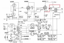
Something like this maybe, Twin/Crazy drive. The 4D32 is one of those zero bias types. Seems to be where Twin/Crazy drive got started even. Requires a power tube to drive it though. Might linearize the plate curves too. (like for 26LX6 seen below)
https://frank.pocnet.net/sheets/201/4/4D32.pdf
You might be better off getting a 4D32. The Raytheon specs sure improved over the type 52.
Might need some dangerous plate voltage though. (ehh, looks like only 550V B+ on the schematic, usually these xmitting tube types are up in the +1000V territory, 4D32 can do real current it seems)
Attachments
Last edited:
> 4D32 is one of those zero bias types.
Not zero-biased in any of the suggested operating conditions.
Appears to be about TEN times the tube of the '52. 3.8 Amps heater??
Looks like the highest plate voltage for un-melted zero-bias operation is 80V, and that is far below the knee.
Your attached plan does show positive grid, but also a low G2 voltage. Many things are possible.
"Only" $80, not costly for a 50W transmitter pentode.
I think this is somewhat off-topic for aldovan.
I was mainly indicating the unusual schematic drive method shown above as applicable to the type 50 tube (using positive grid 1). And also a means of using in it SE mode if desired.
The 4D32 would be an altogether different level of Watts output for sure, compared to the type 50, but probably cheaper at just $25, here:
RAYTHEON JAN 4D32 TUBE | eBay
4D32 is capable of positive grid 1 operation. So with it's Mu g2/g1 of 6.6, it would be essentially a zero bias tube when using just +50V on grid2. The non-typical Twin/Crazy drive used in the 4D32 schematic above starts with 0V on grid1 AND grid2, so clearly meets the zero bias condition. (when used in a class aB push-pull arrangement) (SE is biased half way up for class A of course.)
Last edited:
One could also play the grid1 / grid2 trade-off game with the type 52. Pick the +grid1 plate curve you want for the 0V grid voltage. Multiply that +Vg1 by the Mu factor +1 , ie, (5.2 + 1), and that is the new grid2 voltage needed.
For example, say you want the new Vg1=0 plate knee to be at 35 mA, so pick the existing +18V curve. Then 18 x (5.2 + 1) = 112 V
So +112 V on grid 2 will get you near a 35 mA knee with 0V on grid 1.
Probably call the +180V limit for the plate as a limit for Vg2 also. (graph 2 has grid 2 connected to the plate after all) So +112V on grid2 should be fine.
Last edited:
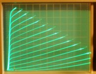
Type 52 transfer curves
Another diyaudio member was kind enough to trace the Type 52 curves for me from a sample I provided - I think that Raytheon's published curves from 1937 are OK, give or take the usual variance from valve to valve.
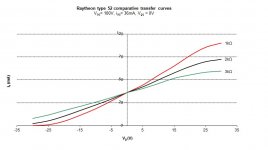
I used the published curves to develop the transfer function for three loads (1kOhm, 2kOhm and 3kOhm) with 100V on the plate, Vg=0V and Ia=36mA. Swinging +-30V:
Another diyaudio member was kind enough to trace the Type 52 curves for me from a sample I provided - I think that Raytheon's published curves from 1937 are OK, give or take the usual variance from valve to valve.
I used the published curves to develop the transfer function for three loads (1kOhm, 2kOhm and 3kOhm) with 100V on the plate, Vg=0V and Ia=36mA. Swinging +-30V:
- 1 kOhm gave 1 Watt @ 10%THD
- 2 kOhm gave 1.2 Watts @ 2.5% THD
- 3 kOhm gave 1.1 Watts @ 5% THD
Attachments
- Status
- Not open for further replies.
- Home
- Amplifiers
- Tubes / Valves
- Question about type 52 tube