Hello all, I have a question about a circuit I have problems with and looking for help, but it requires some intro to the situation. I will try to keep it short.
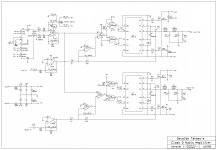
I have a broken class D amplifier from the early 00's which I made an attempt to repair.
The problem was narrowed down to a pwm driver board, and further to a faulty IC on the driver board.
The pwm driver in question consists of an error amp, triangular wave generator, and a comparator that does the actual pwm. It's supposed to oscillate at a fixed 100kHz freq.
I replaced the faulty chip with a combination of LM319 dual comparator and TL072 dual opamp.
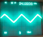
The driver is back to life but I can't get the desired 100kHz
frequency from the triangular generator, the generator oscillates only at 24kHz.
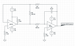
The generator consists of a comparator (half lm319) and an integrator (half tl072).
Below is a (crude) schematic of the triangular gen in question
The measured voltages in the real circuit is -9v for -9v and +9.4v and for +9v.
I've tried to calculate the output frequency from the values of the components and it should oscillate at freq above 100kHz, but it doesn't. But I'm not very confident in my math.
I also tried to reduce the C1 to 8pf and R1 to 100kOhm, this increased the frequency only to 30kHz.
So what I don't know and can't understand is the other factors that may influence the frequency.
Could it be some parasitic capacitance somewhere or 100kHz is too low frequency for this to play any role?
In other words I'm stuck with this and any suggestions will be much appreciated!
I have a broken class D amplifier from the early 00's which I made an attempt to repair.
The problem was narrowed down to a pwm driver board, and further to a faulty IC on the driver board.
The pwm driver in question consists of an error amp, triangular wave generator, and a comparator that does the actual pwm. It's supposed to oscillate at a fixed 100kHz freq.
I replaced the faulty chip with a combination of LM319 dual comparator and TL072 dual opamp.
The driver is back to life but I can't get the desired 100kHz
frequency from the triangular generator, the generator oscillates only at 24kHz.
The generator consists of a comparator (half lm319) and an integrator (half tl072).
Below is a (crude) schematic of the triangular gen in question
The measured voltages in the real circuit is -9v for -9v and +9.4v and for +9v.
I've tried to calculate the output frequency from the values of the components and it should oscillate at freq above 100kHz, but it doesn't. But I'm not very confident in my math.
I also tried to reduce the C1 to 8pf and R1 to 100kOhm, this increased the frequency only to 30kHz.
So what I don't know and can't understand is the other factors that may influence the frequency.
Could it be some parasitic capacitance somewhere or 100kHz is too low frequency for this to play any role?
In other words I'm stuck with this and any suggestions will be much appreciated!
Attachments

If the circuit was working ok previously then maybe one of the two IC's has gone faulty.
Otherwise decrease R1.
Otherwise decrease R1.
Thank you for suggestions, I already tried to replace both lm319 and tl072 to no avail - the freq remains the same.
With 8pf in place and 100k as R1 this circuit should oscillate well over 300kHz if I calculate it with even remotely correct math.
But I'll try to reduce R1 to maybe 50kOhm to see what will happen.
I will try faster opamp and, maybe, the comparator too, if this will not help.
Thank you!
With 8pf in place and 100k as R1 this circuit should oscillate well over 300kHz if I calculate it with even remotely correct math.
But I'll try to reduce R1 to maybe 50kOhm to see what will happen.
I will try faster opamp and, maybe, the comparator too, if this will not help.
Thank you!
Last edited:
8pf is way too small. Parasitic capacitance from op amp and pcb will be dominate the whole circuit together with leakage. Did you use the original circuit and just replaced the op amp or did you replace it with your own circuit. Your cap should be at least a 100× more to actually rise above parasitic elements.
The time constant of your RC circuit is about 1 MHz. You sure the circuit is right. I would use s cap value of 1nf and adjust the resistor to suit.
Oon
The time constant of your RC circuit is about 1 MHz. You sure the circuit is right. I would use s cap value of 1nf and adjust the resistor to suit.
Oon
Last edited:
8pf is way too small. Parasitic capacitance from op amp and pcb will be dominate the whole circuit together with leakage. Did you use the original circuit and just replaced the op amp or did you replace it with your own circuit.
Oon
It is an original circuit, the only thing changed is an IC,
There is no original schematic available, so cap value is a measured value of a desoldered capacitor, all resistors have markings so their values are correct.
I agree that the pf range seems to small for such a circuit but it is what I have.
I will experiment more with different RC combinations
I ran your circuit through LTSPICE and the frequency is around 55KHz.
Thank you for that! I should have done this myself (have to learn spice) Strange that its not achieving 100kHz.
Maybe the original circuit never oscillated at it's declared freq,
don't know.
TL072 is nothing like fast enough to generate a good 100kHz triangle wave, its only got a 3MHz GBP so there's almost no spare gain left to be linear across the wide harmonic spectrum of a triangle wave. A 25 to 40MHz GBP opamp should be findable and do a nice precise job.
Last edited:
To start things I've "carefully calculated" and tried another combination of RC - 1nf - 6.3kohm, same ic's, the frequency remains the same (22kHz), both triangle and meander look much worse.
I'm thinking maybe grab myself some opa2134 to try as integrator, I can get it today, as for super high speed opamps I will have to wait for a couple of weeks.
I'm thinking maybe grab myself some opa2134 to try as integrator, I can get it today, as for super high speed opamps I will have to wait for a couple of weeks.
Well, it was op amp after all, I've installed a fresh opa2134 and I can get frequencies from 84Khz to 112KHz depending on RC values installed no problem.
I'm still not completely sure why using tl072 didn't work. Yes, its slower, but the original circuit almost certainly consisted of very similar op amp. Now I'm thinking maybe my tl072's are remarked fakes? It's unlikely, but possible.
Anyway, thank you for all the suggestions - the discussion really helped to narrow down possibilities.
- Home
- Amplifiers
- Class D
- Question about triangular wave generator circuit