The problem with pot is that it tends to cut the high frequencies at low volume and that is also a reason why in these days no hi-fi company uses pots to attenuate signal. .
I don't know why myths like this persist. Pots do not, of themselves, cause a loss of high frequencies. Using too high a value pot just before a poorly designed high gain triode stage with high Miller capacitance will affect HF response but that is the fault of the design not the pot. All professional audio chains use pots so the music you play will certainly have passed though several before it reaches you without any HF loss.
Cheers
Ian
If you have a high value potentiomer, like 100k ohms, its worst-case output impedance will be high-ish (25k ohms for a 100k ohm pot).
If the series resistance of the incoming signal is 25k ohms, and the input capacitance of the gain stage is high - let's say 300pF - then the high frequency roll-off will be -3dB a 21kHz, which would attenuate the very highest audible frequencies.
If you reduce the value of the pot to 50k ohms, the worst-case high frequency roll-off is now moved up to 42kHz. There will still be some attenuation at 20kHz (maybe -0.1dB), but it will be inaudible.
If you reduce the value of the pot to 50k ohms and change the gain stage to a triode with input capacitance of 75pF, the worst-case high frequency roll-off will be -3dB at 170kHz and will be completely inaudible.
There's nothing wrong with the potentiometer in and of itself. It depends on whether or not you design your circuit properly for the desired results.
--
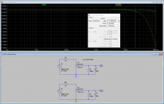
I duplicated your experiment with a 50k pot, assuming a source output resistance of 1k and the 300p Miller capacitance you mentioned in parallel with a 1 megohm grid leak resistor, and got the same results. See attached simulation screen shot.
The green plot is taken with the pot at full clockwise (no attenuation) and the brown plot is the response with the pot at 10% electrical rotation. Both curves have been normalized for an output level of 0 dB to make the comparison easier. The 10% rotation display does show a high frequency roll off but it's still down only about 0.1 dB at 20 KHz. I personally would not concern myself with this.
The green plot is taken with the pot at full clockwise (no attenuation) and the brown plot is the response with the pot at 10% electrical rotation. Both curves have been normalized for an output level of 0 dB to make the comparison easier. The 10% rotation display does show a high frequency roll off but it's still down only about 0.1 dB at 20 KHz. I personally would not concern myself with this.
Attachments
For a high value pot you could probably add a capacitor between input and wiper for compensation 😀
Adjust the pot to 50% attenuation, with the wiper at exactly half the resistance of the pot (so at 25k from wiper to top, 25k wiper to bottom). That's the spot where the output resistance of the pot is 1/4 the value of the pot (12.5k ohms for a 50k ohm pot).
On a linear taper pot this should be at half rotation, but with a log taper pot the mid-point will not be at the center of rotation.
On a linear taper pot this should be at half rotation, but with a log taper pot the mid-point will not be at the center of rotation.
For a high value pot you could probably add a capacitor between input and wiper for compensation 😀
How does that work?
Compensation?
Cancellation of the load capacitance on the wiper (output) of the pot?
??
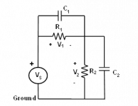
Compensated frequency divider ... for any "high" frequency you need this for flat response .
C1 is added to compensate the loss from C2 wich is the input capacitance of the stage .
The only problem is that the R values are not constant , obviously .
C1 is added to compensate the loss from C2 wich is the input capacitance of the stage .
The only problem is that the R values are not constant , obviously .
Attachments
Last edited:
How would you choose the value of C1? Can it be an approximate value, or do you have to closely match the input capacitance of the driven stage?
For fixed resistors if you know exactly the input capacitance can be calculated easily , if not , just tweek the value until you are satisfied with the frequency response .
If you have a high value potentiomer, like 100k ohms, its worst-case output impedance will be high-ish (25k ohms for a 100k ohm pot).
If the series resistance of the incoming signal is 25k ohms, and the input capacitance of the gain stage is high - let's say 300pF - then the high frequency roll-off will be -3dB a 21kHz, which would attenuate the very highest audible frequencies.
--
I am pretty sure 300pF is never likely to occur in practice. Even a 12AX7 stage is unlikely to have a gain of more than 70 which gives a Miller capacitance of just 119pF. This moves the 3dB point to 53Khz.
100K is far to high a value for a pot. All today's sources will drive 10K which moves the 3dB point out to over 250KHz.
With reasonably competent design, pots and Miller are not an issue.
Cheers
Ian
I am pretty sure 300pF is never likely to occur in practice.
Well, there is the fad for 'passive preamp', even in a high impedance tube-based signal chain, right where it doesn't belong. A 2-meter interconnect can easily have 300pF of capacitance.
But yes, true, in a line stage like at the input of a power amp you won't see 300pF shunt load. But 200pF? Maybe...
12AX7 Cga = 1.6pF, add 0.8pF for stray C = 2.4pF
Cgk = 1.6pF as well, add 0.8pF for stray C = 2.4pF
Cgk + Cga(A+1)
2.4pF + 2.4pF(71) = 172.8pF
True, it's not necessary to use a 100k pot any more -except- if the preceding stage is something like a tube phono preamp with an output impedance of >/= 10k ohms, like if you use a 12AT7 or 6SN7 common cathode stage for the output. That's actually possible.
With reasonably competent design, pots and Miller are not an issue.
Well, yeah. Of course. You're expecting universal competence??
For a high value pot you could probably add a capacitor between input and wiper for compensation 😀
That would be only at one setting of the volume pot, and then would either peak or roll off at other settings,
not such a good idea. That's just a musician's amp trick, not for audio.
How would you choose the value of C1? Can it be an approximate value,
or do you have to closely match the input capacitance of the driven stage?
R1 x C1 = R2 x C2
See scope probe compensation articles.
Right, but for a *variable* resistor? As you pointed out in the post before this last one, changing the position of the pot would change R but not C, changing the time constant of the parallel RC.
Right?
Right?
Yes, that's why it's a bad idea for audio. HK did use peaking capacitors in their tube amps,
but that was at locations such as fixed grid impedances, not on volume controls.
Harman Kardon Citation II Stereo Power Amplifier Manual | HiFi Engine
This CAN be done in some kinds of switched resistor volume controls, where you would use
separate capacitors (of varying values) in parallel with each of the series resistors.
But this is not really needed for ss circuits, which typically use 10k controls.
Last edited:
Wx
Well, yeah. Of course. You're expecting universal competence??
That would be too much to ask. I just think the myth that pots are intrinsically bad needs to be dispelled.
Cheers
Ian
That´s why it´s better to solve the problem at the root (use an adequate value pot) and not apply bandages.Right, but for a *variable* resistor? As you pointed out in the post before this last one, changing the position of the pot would change R but not C, changing the time constant of the parallel RC.
Right?
And in general doing things the right way, not for imagined/mystical ones.
I read about nonsense such as "passive preamps" and my blood boils 🙄 ; the supposed "solution" to a non-problem only creates new ones, much worse in degrading effect.
Just add a unity gain buffer after the wiper and drive anything you want, how´s that?
Just imagine the WIDE frequency response and vanishing distortion of a unity gain stage, compare that to incompetently driving any real world cable and next Audio stage input.
I just think the myth that pots are intrinsically bad needs to be dispelled.I just think the myth that pots are intrinsically bad needs to be dispelled.
That´s why it´s better to solve the problem at the root (use an adequate value pot) and not apply bandages.
And in general doing things the right way, not for imagined/mystical ones.
You all are making far too much sense.
🙂
- Home
- Amplifiers
- Tubes / Valves
- Question about preamp design and headroom