Hi,
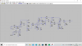
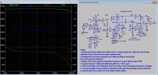
Recently, one of my teachers came to me and asked me if I could design and build a tube amp for him. So I got excited and started to work. Here I came up with preamp section which uses 12AT7 as a gain cell where the gain of upper tube tube is controled by the voltage on the grid of the lower tube. Then there is a EF86 and one half on 12AU7. As the power tube I chose a KT88 but I dont have it in schematic because I couldn't find the right output transformer model. At the full volume the preamp makes at the output 250V from the 1V input. Do you think, that this design should be working well? Isn't that 250V too much for KT88? Is there any way how to calculate tube headroom? Thank you very much.
Recently, one of my teachers came to me and asked me if I could design and build a tube amp for him. So I got excited and started to work. Here I came up with preamp section which uses 12AT7 as a gain cell where the gain of upper tube tube is controled by the voltage on the grid of the lower tube. Then there is a EF86 and one half on 12AU7. As the power tube I chose a KT88 but I dont have it in schematic because I couldn't find the right output transformer model. At the full volume the preamp makes at the output 250V from the 1V input. Do you think, that this design should be working well? Isn't that 250V too much for KT88? Is there any way how to calculate tube headroom? Thank you very much.
Attachments
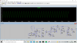
So a computer simulation of your circuit produces 250 V signal at the output?
The cathode voltage of the 12AU7 would be around -1 V (at Ia = 10 mA and Va = 120 V). The gain stage is about 12. So to reach an output voltage of 250 V an input voltage of almost 21 V is needed. I don't really see how there is room for that with Vg being only - 1V.
I don't really get the idea behind the 12AT7 stage. If I understand your description correctly, the input of the amplifier is at the upper section of the 12AT7. That section is grounded through R13. The lower section seems to function like a kind of cathode bias resistor for the upper section. There's 20 V on the control grid of the lower section while at the same time hardly any voltage can develop between its cathode and anode since that voltage is the same as the cathode voltage, so the bias, of the upper section. I would think that grid current will flow in the lower section of the 12AT7. What is the benefit of this idea?
Yes, there is 21V on the input of the 12AU7. I know that the bias voltage isn't high but the simulation shows that it is working but I'm not sure if is it working irl. The idea behind the 12AT7 stage is to have a volume control without the signal passing trough the pot. Yes you were right, the lower 12AT7 acts like a variable cathode resistor.
From where is that idea of electronic pot ? I don't think has any chance of working in real world ...
That is just something that I came with. Why do you think that it would not work irl? Simulation shows that it works.
No chance of working right , how do you think a variable cathode resistor is adjusting the volume ? It would have been used from 100 years ago 😀
I've already build that but in a simpler version. By changing the value of cathode resistor you can really adjust the volume.
1) congratulations on rolling up your sleeves and actually designing/simulating/building/testing something 🙂
2) that said, you have some doubts, ask here, will get answers, maybe you don´t like some of them, but hey, that´s how it works 🙂
3) a few of us, me included, have an issue with using a variable resistor at first stage cathode as gain control, and doubly so by using a tube there.
MAIN problem is that it will also vary the DC working points, BIG TIME.
Gain tube bias will vary, plate voltage, signal symmetry, saturation, lots of problems which far outweigh the possible convenience.
With high attenuation sound may even become "choppy", like a poorly adjusted Noise Gate,and needlessly distorted.
Add to that the gain control tube in series with cathode is working with less than 2V plate voltage, completely outside its expected working point.
IF anything, you will get much better results by using a plain silicon bipolar transistor there, go figure.
Another BIG problem is that Control signal appears at the output, and it will be much higher than actual Audio signal.
Tube Audio compressors do vary gain/volume electronically, that´s their purpose, but to avoid those problems work in a symmetrical/balanced circuit and at the end stage they add signals out of phase, so they keep Audio but null volume control voltage, go figure.
It is so important to do that, that they often add a precision Null trimmer to fully make it disappear.
IF you made a balanced input stage and nulled control voltage, then it would be more practical
For reference, a classic Tube Compressor/Limiter
Audio signal is rectified into DC by double diode V3 6AL5 charging 1uF capacitor C4 and that DC is fed to V1 grids to directly control their gain, nothing on cathodes.
Yes, their bias varies wildly, also plate voltages (what happens in your design too) but they null it out at the output transformer T2

As of your 250V output level:
4) you have very high gain throughout, so you WILL get high signal levels at the output.
5) you stipulated a high signal level at the input.
What will the actual signal/Music source be?
EDIT: IF you want electronic volume control, you may use a CDS LDR as a variable resistor and drive it with a LED.
There is a thread or two at this Forum discussing that.
2) that said, you have some doubts, ask here, will get answers, maybe you don´t like some of them, but hey, that´s how it works 🙂
3) a few of us, me included, have an issue with using a variable resistor at first stage cathode as gain control, and doubly so by using a tube there.
MAIN problem is that it will also vary the DC working points, BIG TIME.
Gain tube bias will vary, plate voltage, signal symmetry, saturation, lots of problems which far outweigh the possible convenience.
With high attenuation sound may even become "choppy", like a poorly adjusted Noise Gate,and needlessly distorted.
Add to that the gain control tube in series with cathode is working with less than 2V plate voltage, completely outside its expected working point.
IF anything, you will get much better results by using a plain silicon bipolar transistor there, go figure.
Another BIG problem is that Control signal appears at the output, and it will be much higher than actual Audio signal.
Tube Audio compressors do vary gain/volume electronically, that´s their purpose, but to avoid those problems work in a symmetrical/balanced circuit and at the end stage they add signals out of phase, so they keep Audio but null volume control voltage, go figure.
It is so important to do that, that they often add a precision Null trimmer to fully make it disappear.
IF you made a balanced input stage and nulled control voltage, then it would be more practical
For reference, a classic Tube Compressor/Limiter
Audio signal is rectified into DC by double diode V3 6AL5 charging 1uF capacitor C4 and that DC is fed to V1 grids to directly control their gain, nothing on cathodes.
Yes, their bias varies wildly, also plate voltages (what happens in your design too) but they null it out at the output transformer T2
As of your 250V output level:
4) you have very high gain throughout, so you WILL get high signal levels at the output.
5) you stipulated a high signal level at the input.
What will the actual signal/Music source be?
EDIT: IF you want electronic volume control, you may use a CDS LDR as a variable resistor and drive it with a LED.
There is a thread or two at this Forum discussing that.
Last edited:
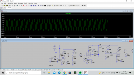
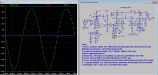
Thank you for your reply. The audio source will be I think CD player. If I got it right from what you said, I can vary the gain also by the voltage on the grid? I tried this and it seems to me that it works. What do you think. Resistor R18 is the one that varies.
Attachments
Changing the voltage on the grid will change the DC operating point just like using a variable resistor in the cathode circuit.
Why not just use a pot?
Why not just use a pot?
If you're really bored, you could use a MAS6116 analog volume chip...
"MAS6116 is designed for high-end audio systems where the volume control is done in the analog domain for best performance. "
MAS6116 – Stereo Digital Volume Control IC | Micro Analog Systems
"MAS6116 is designed for high-end audio systems where the volume control is done in the analog domain for best performance. "
MAS6116 – Stereo Digital Volume Control IC | Micro Analog Systems
@ Tom Vyborny,
I've read through this thread a few times and it's still not completely clear what you attempting to do. The thread title says "preamp design" but then you mention a KT88 power amplifier. Are you trying to design a true preamplifier, or the driver stage for a power amplifier? Those are two very different applications. It really looks like this circuit is intended to be a power amplifier driver with a volume control added.
A typical preamp, especially one that will be driven from a high-level source like a CD player, generally requires very little voltage gain, maybe x3 or x4 (10 to 12 dB). With a 1 volt input signal you will get only about 4 volts out, so "headroom" is a non-issue in a tube preamplifier unless the operating points are nowhere near center bias.
A power amp driver, on the other hand, usually provides significant gain if global feedback is used, or a more modest amount of gain in a non-feedback design. You haven't given any clear indication about what the end product is supposed to be, but if you actually have a power amplifier in mind then the first decision that needs to be made is what the desired power output should be. Only then can you determine the output tube drive voltage requirements and therefore the gain requirements of the driver stage(s). But I can say with reasonable certainty that you don't need a voltage swing anywhere near 250 volts to drive a typical KT88 output stage.
I agree with others here that trying to use variable gain as a form of volume control is ill advised and introduces unnecessary complications. A level control consisting of a typical audio taper potentiometer is the usual approach, and for good reasons. If the volume control is placed at the output of a preamp (or the input of a power amp), it will attenuate noise along with the signal. A gain control will not do that, nor will a gain control be able to turn the volume "all the way down" if that is a requirement.
As an additional suggestion, using SPICE as your primary design tool isn't a good idea. It's far better to come up with a design using load lines, tube datasheets, etc. and then use SPICE as a tool to verify that the design works the way it's supposed to (or doesn't!).
There are a lot of experienced designers on this forum. If you can be a little clearer about what you are trying to accomplish, you will likely get more useful advice. And as a first project, you might be better off building a proven design instead of starting from scratch. There are a lot of well-documented designs in this forum to choose from.
Good luck.
Last edited:
Yes, it is meant to be driver section for the KT88. The problem with pot is that it tends to cut the high frequencies at low volume and that is also a reason why in these days no hi-fi company uses pots to attenuate signal. For example PS Audio uses what they call "Gain cell" which is what the founder said tube section with variable gain by varying the cathode resistor. And like I said I already tried that irl in one of my preamps and it really works. Only problem that I got is that I cant get volume as low as with pot. In this case I wanted to try something new. Don't worry, this isn't my first project🙂.
The PS Audio gain cell has been discussed in these forums before. As you might expect, opinions vary but one reviewer was less than impressed.
Conventional pot vs. PS Audio gain cell
But this is DIY after all. 🙂
Conventional pot vs. PS Audio gain cell
But this is DIY after all. 🙂
The problem with pot is that it tends to cut the high frequencies at low volume...
I don't understand why that would happen. Would you explain how it works?
- Home
- Amplifiers
- Tubes / Valves
- Question about preamp design and headroom