I have an audio source that always outputs a signal that is about half the volume as it should be.
What would be the downsides of simply using 4 audio isolation transformers to step up the voltage 2x before sending it off to the amplifier?
The reason for using 1:1 audio isolation transformers is they are cheap, easy to find, and already optimized for audio frequencies.
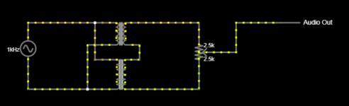
Something like this(This is only half, as there are 2 channels):
What would be the downsides of simply using 4 audio isolation transformers to step up the voltage 2x before sending it off to the amplifier?
The reason for using 1:1 audio isolation transformers is they are cheap, easy to find, and already optimized for audio frequencies.
Something like this(This is only half, as there are 2 channels):
Attachments
Technically, it can work.
But I don´t much see the point of using 4 transformers to get a mere 6dB voltage gain, where there are easier options.
You don´t give us any details at all, such as what is your audio source or what the amplifiers are (hint hint) but I guess you can either increase source out or power amp sensitivity ... IF any of those are really needed that is.
Are you sure you need exact 6dB gain?
We need details. 🙂
What would be the downsides of simply using 4 audio isolation transformers
to step up the voltage 2x before sending it off to the amplifier?
You only need 1 per channel.
Attachments

You only need 1 per channel.
I didn't know you can do that! Thanks.
The output is analog from my TV going to the amp that powers the speakers. The output from the TV is low, but not that low, but I thought I could save a wire by doing it passive, and keep things tidy. Yes, 6DB should do it, it needs just a bit more. I thought it would be a solution over running a preamp between the TV and amplifier, as when I do that, I have to ground loop isolate anyways due to ground loop noise. Audio isolation transformers are like 50 cents each, so don't think it's a matter of cost 😛
It appears that Rayma's doesn't actually isolate though, so perhaps that isn't really a solution unless the active preamp was the source of the ground loop noise all along.
Last edited:
I thought it would be a solution over running a preamp between the TV and amplifier,
as when I do that, I have to ground loop isolate anyways due to ground loop noise.
If you really do need galvanic isolation, use the circuit with 2 transformers per channel.
Some audio transformers do have 2 secondary windings, though.
Distotion, particularly at low frequencies.I have an audio source that always outputs a signal that is about half the volume as it should be.
What would be the downsides of simply using 4 audio isolation transformers to step up the voltage 2x before sending it off to the amplifier?
Frequency response not perfect, especially without the right output network.
Bass power handling is a limiting factor, as this is where saturation will happen first.
Hum pickup if not well screen magnetically and kept away from hum sources.
Size/weight?
So a little care is needed in checking the impedance matching and response to get flat response, and bass handling might be an issue if the Xformer is too small.
Being passive is obviously an advantage for simplicity.
The reason for using 1:1 audio isolation transformers is they are cheap, easy to find, and already optimized for audio frequencies.
Something like this(This is only half, as there are 2 channels):
Distotion, particularly at low frequencies.
Frequency response not perfect, especially without the right output network.
Bass power handling is a limiting factor, as this is where saturation will happen first.
Hum pickup if not well screen magnetically and kept away from hum sources.
Size/weight?
So a little care is needed in checking the impedance matching and response to get flat response, and bass handling might be an issue if the Xformer is too small.
Being passive is obviously an advantage for simplicity.
I see. I kept the isolation and stepping up on the high impedance side to help with the distortion. Just hooked it all up today, as I figured I would just give it a shot, and I am not sure I notice any effect to sound quality other than a positive one from having high enough volume levels now. I suppose I lucked out here if so much could have gone wrong.
I have it enclosed in an Altoids tin, should that be enough shielding(Although currently I hear no noise getting in).
I think you need to define cheap. Cheap audio transformers are usually hot garbage with limited frequency response and phase shift amongst other issues. A line-level 600:600 transformer of good quality like the Jensen JT-11P-1 will cost about $60. You will need two per channel in this case- that comes out to about $240. If you shop around you could find a pair of 10K:600 Jensens for that price. I've seen JE-6110K-B transformers go for as low as $40 each.
But IMO, a 5532 (or even a TL072) and a pair of 600:600 transformers could do a better job for less than $100. This allows you to use the pot for a gain control, rather than an attenuator, and you will be able to get a lower noise floor. And I would hazard a guess than 90%+ of the music available has already passed through at least 20 5532s and/or TL072s in the desk it was recorded through, so I wouldn't worry about putting it through one more.
Also, I am assuming that if you're throwing a bunch of transformers at the issue you want to go balanced. Your attenuator, as drawn, will not do that. If you don't need balanced, why the transformers?
I have an audio source that always outputs a signal that is about half the volume as it should be.
What would be the downsides of simply using 4 audio isolation transformers to step up the voltage 2x before sending it off to the amplifier?
The reason for using 1:1 audio isolation transformers is they are cheap, easy to find, and already optimized for audio frequencies.
Something like this(This is only half, as there are 2 channels):
Why transformers? They pick up hum and have lousy low frequency response and measure bad THD at the low end. What's wrong with an opamp? Fast, quiet, low THD. 6-10 dB is a walk in the park. 20 resistors or so, a few caps and you're good to go.
Personally, my latest project has no coupling caps input or output so goes to DC. Offset is barely measurable. Built it on a 4 layer board with a ground plane. KiCad to make the PCB and sent the files to JLCPCB in China. Files were sent on a Wednesday and had the boards the following Tuesday. Used 0.5% thin film 0805 resistors and 2% film caps in the tone control networks. So far it measures very well. Only 'lytics are a pair of 2200uF 16 V polymers for the power supply. All the 10 and 100uF caps are MLCC ceramics.
Try it. It's fun.
G²
+1. Transformers have their place, but I struggle to see the advantage of using them here.
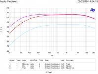
Here are actual curves from a Triad TY-145P transformer and a Mouser 42TL016-RC. For better low frequency response the Triad TY-146P can be used. The high frequency roll-off is in the circuit used not the transformers. (Funny don't see any hum pick-up! Used just free air on my bench.)
All are 600 Ohm to 600 Ohm center tapped so use the input on the center tap and the output across the entire winding.
Completely under $25.00.
All are 600 Ohm to 600 Ohm center tapped so use the input on the center tap and the output across the entire winding.
Completely under $25.00.
Attachments
Last edited:
Here are actual curves from a Triad TY-145P transformer and a Mouser 42TL016-RC. For better low frequency response the Triad TY-146P can be used. The high frequency roll-off is in the circuit used not the transformers. (Funny don't see any hum pick-up! Used just free air on my bench.)
All are 600 Ohm to 600 Ohm center tapped so use the input on the center tap and the output across the entire winding.
Completely under $25.00.
Wow. Wasn't expecting anything this in depth 😀 Is that the response with a load? I didn't notice anything that severe, but the input impedance of the amp I am using is very high. I used EI-14 transformers.
+1. Transformers have their place, but I struggle to see the advantage of using them here.
Ground loop isolation + line level boost without having another cord to plug in, that's all.
Last edited:
Doing a project that will end up using 20,000 or more of them. Source impedance is 660 ohms load is 10,000 ohms. I show the same transformer at two levels which suprisingly shows it is not saturation rolloff on the low end. But they are tiny transformers.
I use the TY-146 models by the hundreds, never had a problem.
I use the TY-146 models by the hundreds, never had a problem.
The other really good application for transformers is that transformer balanced inputs work really well for things like microphones. Their bandwidth limiting at the high end also has the positive side effect of blocking RF.
The (likely quite high) distortion and poor frequency response of the Triad makes it something I wouldn't want in the signal path of a high-fidelity system. IMO, for high-fidelity recording and reproduction, if you can't afford good transformers in a design, don't include them at all. Of course there are exceptions to this, but this sounds like an application where a TL072 makes more sense. Lack of a power supply with the transformers is an advantage, but you will lose load-driving capability and unless you spend a lot of money, you're going to limit your bandwidth as well, especially on the low end.
You might look at what Edcor has to offer for line transformers. They have line transformers with the impedance ratios that you're looking for. Expect to spend about $25 each. They don't have nickel cores and I wouldn't expect the world, but they might work okay for what you want to do. Only big downside is the lead time that ranges from 2-8 weeks.
The other really good application for transformers is that transformer balanced inputs work really well for things like microphones. Their bandwidth limiting at the high end also has the positive side effect of blocking RF.
The (likely quite high) distortion and poor frequency response of the Triad makes it something I wouldn't want in the signal path of a high-fidelity system. IMO, for high-fidelity recording and reproduction, if you can't afford good transformers in a design, don't include them at all. Of course there are exceptions to this, but this sounds like an application where a TL072 makes more sense. Lack of a power supply with the transformers is an advantage, but you will lose load-driving capability and unless you spend a lot of money, you're going to limit your bandwidth as well, especially on the low end.
You might look at what Edcor has to offer for line transformers. They have line transformers with the impedance ratios that you're looking for. Expect to spend about $25 each. They don't have nickel cores and I wouldn't expect the world, but they might work okay for what you want to do. Only big downside is the lead time that ranges from 2-8 weeks.
What you need to understand is, this was done for my mother who is quite advanced at living if you catch my drift 🙂
It was done so that she can hear the TV better, and less wall rattling low end is a good thing.(I gifted her a stereo system a couple Christmases ago, and it can sound like a movie theater in there sometimes).
Less wires(as this box doesn't even need to be removed) is also a good thing. She tends to get confused when too many things need to be plugged in. She can't hearing anything on the extreme high end either, so there is no point in preserving all of that. It has worked for her purposes.
She can hear the TV better now, even if it is mostly because of distortion caused by the transformers acting as a 'loudness' boost. Even still, I am not sure I would notice it as someone with healthy hearing, but she can now get volumes where she can hear the tv without turning everything up to max and still need subtitles turned on. In fact, I think she keeps the tv at LOWER levels than before now. Also, since it is getting rid of the ground loop, the noise is inaudible when she does have it turned all of the way up.
Maybe this will make the entire logic behind me doing this make more sense.
It absolutely would make no sense for most people, but I actually do think it COULD act as a fairly decent loudness filter, although that was an unintended helpful side effect.
Last edited:
What you need to understand is, this was done for my mother who is quite advanced at living if you catch my drift 🙂
It was done so that she can hear the TV better, and less wall rattling low end is a good thing.(I gifted her a stereo system a couple Christmases ago, and it can sound like a movie theater in there sometimes).
Less wires(as this box doesn't even need to be removed) is also a good thing. She tends to get confused when too many things need to be plugged in. She can't hearing anything on the extreme high end either, so there is no point in preserving all of that. It has worked for her purposes.
She can hear the TV better now, even if it is mostly because of distortion caused by the transformers acting as a 'loudness' boost. Even still, I am not sure I would notice it as someone with healthy hearing, but she can now get volumes where she can hear the tv without turning everything up to max and still need subtitles turned on. In fact, I think she keeps the tv at LOWER levels than before now. Also, since it is getting rid of the ground loop, the noise is inaudible when she does have it turned all of the way up.
Maybe this will make the entire logic behind me doing this make more sense.
It absolutely would make no sense for most people, but I actually do think it COULD act as a fairly decent loudness filter, although that was an unintended helpful side effect.
That makes a lot more sense. I know *exactly* what you are talking about with the simplicity. Fewer wires and less complexity means fewer tech support calls. Perfectly valid.
- Status
- Not open for further replies.
- Home
- Source & Line
- Analog Line Level
- Question about passive amplification