Hey people!
I have a question just for curiosity: I foud this amp, a Gradiente Model 80 in a pawn shop for a very cheap price. Its a vintage, with 30 years old but it works perfectly, with all the original components in place.
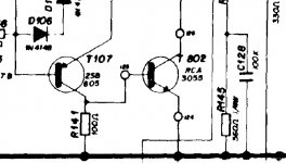
But I was watching the wiring diagram and noticed that the output transistors are two NPN RCA3055.
I'm not a genious in electronics, but I thought that the output transistors should be one NPN and one PNP.
How does a circuit like this works?
Edit: you can find the diagram at http://www.4shared.com/file/17216381/b0ac6fc5/m80.html
I have a question just for curiosity: I foud this amp, a Gradiente Model 80 in a pawn shop for a very cheap price. Its a vintage, with 30 years old but it works perfectly, with all the original components in place.
But I was watching the wiring diagram and noticed that the output transistors are two NPN RCA3055.
I'm not a genious in electronics, but I thought that the output transistors should be one NPN and one PNP.
How does a circuit like this works?
Edit: you can find the diagram at http://www.4shared.com/file/17216381/b0ac6fc5/m80.html
And what about these capacitors in the output? They are foi coupling, right?
What happens if I decrease or increase it's value?
What happens if I decrease or increase it's value?
Quasi-Complementary
The quasi-complementary output using 2 NPN transistors was used because in the mid 60s high power silicon PNP transistors were not really invented yet. They did not come out until about 1970 and we then moved to fully complementary amplifier output stages.
The quasi-complementary output using 2 NPN transistors was used because in the mid 60s high power silicon PNP transistors were not really invented yet. They did not come out until about 1970 and we then moved to fully complementary amplifier output stages.
- Status
- Not open for further replies.
- Home
- Design & Build
- Parts
- Question about output Transistors