Hi, I just found this interesting schematic and I just wondered if my theory about how this amp works is right or not.
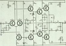
I like this schematic because of it's input stage with two current sources.
If I understand it correctly Q9 en Q4 act like current sources, so when no input connected there will flow following biasing current:
I(bias) = (4.7V - 0.7V)/1820 * Hfe(Q4)
When the input signal (Vi) increases, Vb(Q3) will decrease and
Ic(Q3) will increase. The current through the biasing circuit doesn't change so the current through the base of Q5 will increase.
Q7 and Q8 give the signal a phase shift of 180 degrees that we need for the negative feedback.
When Vi decreases, Ic(Q3) will decrease and Ib(Q6) will raise, etc...
I'm just wondering if C9 is placed over there to prevent that the bias voltage will drop when Ic(Q3) decreases or has this capacitor another function??
thanks,
HB.
Attachments
Thanks Nelson, I'm glad to hear that!!!
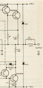
Now, I've still have these questions about the included output stage:
What's the function of D12 and D13?? To protect the transistors against inductive loads?? Is it really necessary to use them?
And what's the exact reason of the 22ohm resistor and the 3µH inductor? I calculated the impedance of it:
Z=(R*jwL) / (R+jwL) w=2*pi*f
Z= (jwRL)(R-jwL) / (R+jwL)(R-jwL)
Z= (w²RL + jwR²L) / (R² + (wL)²)
so it seems that it acts like a low pass filter, is that correct?
Thanks,
HB.
Attachments
hugobross said:
What's the function of D12 and D13?? To protect the transistors against inductive loads?? Is it really necessary to use them?
And what's the exact reason of the 22ohm resistor and the 3µH inductor? I calculated the impedance of it:
so it seems that it acts like a low pass filter, is that correct?
Thanks,
HB.
The diodes are wise to have and correct they take care of currents from inductive load when you abruptly shut off the current. The current through the load (speakers) must go somewhere. If you don't have them you can kill the output stage. (note that MOSFET's have these diodes by nature, not exactly as normal silicone diodes but they do the job pretty good)
The output filter isolates the amp from capacitive load and/or difficult speakers (the same thing more or less) and the value isn't very critical. 0,5-3 µH (15-20 turns normal wire, diam. 10-15 mm) in parallel with 5-22 ohm.
The filter can also block HF picked up from speaker and the cable.
The diodes protect against flyback voltages, and are a
hangover from the old days when V/I limiters were
used for protection. They don't hurt, though, so we leave
them on in case we encounter something really crude for
a load. Mosfet amps don't need them, so you only see them
on Bipolars.
The output coil and resistor are similarly hangovers from the
old days. They were in the original RCA manual, and most
designers use them because monkey-see-monkey-do.
I have never seen a case where they stabilized an unstable
amp, nor where their absence caused instability, and so I
don't use them.
By contrast, the RCA network to ground on the output is
standard and useful for feedback amps. Again, I don't tend
to use them, but I don't usually have enough feedback to
worry about.
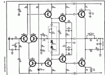
The schematic style is Popular Electronics, not Audio.
The design is a Dan Meyer / SWTP design. Pre-Tiger amps didn't have dual complementary diff amp inputs.
The SS1122/SS1123 transistors seemed to be
a Motorola "special" for SWTP. At lease I never
found them in regular databooks. I always thought
that "SS" stood for "Southwest Special".
The CFP-like outputs with the gain-of-2 setup
was another Dan Meyer "signature" feature.
For the newbies around here, SWTP stands for
Soutwest Technical Prouducts Corp. which did
various kits in the late 60s (?) and early 70s.
If I recall correctly, they were based in San
Antonio, TX. (which geographically is hard
to call southwest, but that's a different topic)
the first amp is by popular electronics 1975
the second application is by RCA, final release in 1972
I found them here: http://www.hilberink.nl/amps/amps.htm
the second application is by RCA, final release in 1972
I found them here: http://www.hilberink.nl/amps/amps.htm
Nelson Pass said:
The output coil and resistor are similarly hangovers from the
old days. They were in the original RCA manual, and most
designers use them because monkey-see-monkey-do.
I have never seen a case where they stabilized an unstable
amp, nor where their absence caused instability, and so I
don't use them.
Well, I found they can be quite useful, but only when using nasty loads. I tried to remove the coils or only replace them with lower values on several commercial designs - sometimes made the amps oscillate heavily when driving a square wave into a 3 R resistive load!
I try to make my own designs stable with all kinds of loads, including 100 pF - 10 uF stacked film capacitors on the output. Found I could not eliminate the coil completely if I did not want to limit the bandwidth but was able to do with 1/100 of what is commonly used.
Eric
Use of output coil is very dependent of what kind of load is connected, but also of phase margin and gain in the overall feedback loop. In fact, this is the same thing because at very high frequencies the amp becomes a current generator, and the reactance of the load is the essential part of the current/voltage converter at the output.
The major problem is that one cannot divine what kind of load can be connected by the artless user... which always reads the carefully prepared "user manual" after the disaster.
Regards, P.Lacombe.
The major problem is that one cannot divine what kind of load can be connected by the artless user... which always reads the carefully prepared "user manual" after the disaster.
Regards, P.Lacombe.
What's the function of D12 and D13?? To protect the transistors against inductive loads?? Is it really necessary to use them?
When I read the article, it seemed to me that the diodes, which are mounted in thermal contact with the 2955/3055 pair, are there to compensate for temperature changes. The diodes are actually base-emitter junctions of 2N4918 transistors, which are in flat, medium power cases (I don't remember the case style. It's not TO220.), so they should make a good thermal/mechanical contact with the TO220 power output trannies.
Did you ever finish this project? How did it go?
And all that time nobody notised the wrong formula the TS statedDear InOr, be aware that you are answering to a thread dead since 2002.

I(bias) = (4.7V - 0.7V)/1820 * Hfe(Q4)
There is a "1" to much, can happen but the Hfe has (allmost)nothing to do with the source(bias) current.
It's simply I(bias) = (4,7V - 0,7V) / 820
Mona
- Status
- This old topic is closed. If you want to reopen this topic, contact a moderator using the "Report Post" button.
- Home
- Amplifiers
- Solid State
- question about input stage of this amp