do bias issues have a particular sound or behavior to them? the amp in question is a 1967 xam integrated made by electro voice. i believe this amp uses germaniums.
at low volume it sounds just like what a speaker with loose voice coil windings sounds like. its almost as if its at the threshold that a transistor is conducting on and off with audio peaks. its full of the epoxy pill shaped transistors which i have heard were problematic.
ideas? unfortunately i dont have a schematic for it. these were made as a house brand to a department store.
No doubt there are people here better versed and more favorably disposed towards germanium. Germanium devices are known for going leaky and freaky. Sometimes you put them on the curve tracer and the whole family points skyward. They go intermittent and can do something different every time you power them up. The parts can look fine with the usual DVM diode check, but unlike a silicon device where a good diode check almost always means the device is good, the germanium will look good and still be bad under power. The circuits are a pita because the low turn-on voltage and leakage make almost all in-circuit measurements suspect. I'd try some freeze mist or heat (use heat very sparingly) to locate a bad transistor. Naturally at the age of the amp it could also have bad caps or other problems.
the amp has been recapped and power supply diodes replaced. the transistors seem to be all original. will try the hot/cold idea when i return to work next week.
From your description it sounds like crossover distortion.
Many germanium stages were really basic, sometimes just a three transistor affair with complementary outputs and driver.
You need to see how they are biased. Some designs had a preset for current, others a fixed bias. It's a fine line as any excess reduces battery life drastically and can also cause thermal runaway. You are problably looking at around 5ma or so in the output pair.
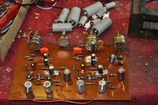
1967 and epoxy pill shaped transistors sound more like early silicon to me, though could be hybrid, (any pictures?).
Agree with Mooly, sounds like crossover distortion, biassing problem?
Agree with Mooly, sounds like crossover distortion, biassing problem?

Thanks for the pics.
They are silicon. For no good reason I assumed it was a battery powered radio...
Power output is obviously limited by just using those TO5 ? outputs.
Are both channels the same as regards the distortion ? A scope check with a generator and correct load impedance would reveal the nature of the distortion.
You still need to determine how the stage is biased and what the standing current is. Next to the output transistors is what looks like a 10 ?? ohm resistor. Is that in series with the emitter or collector of the outputs. If so you can determine current from voltage dropped across it.
Those little ceramic packages with epoxy tops are, IMO, pretty decent. I've seen a lot of FETs in those too. Usually there are part numbers on the perimeters- can you read anything there?
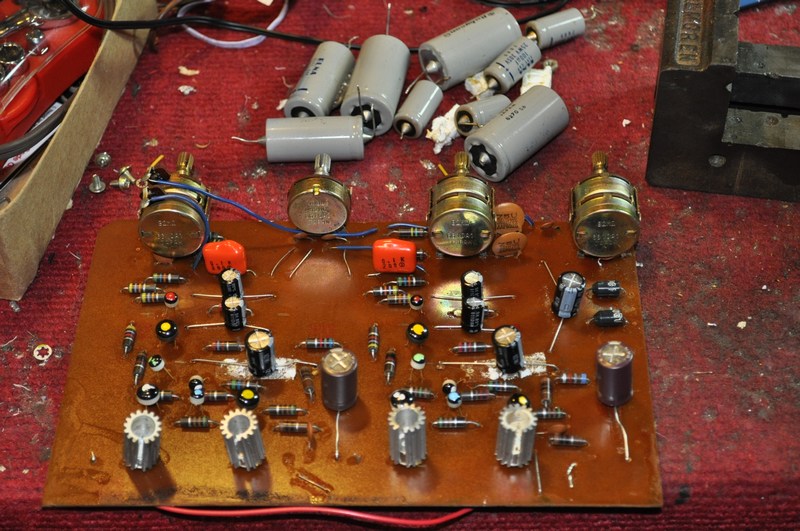
I find gargly sound can come from old electolytic caps. These look pretty old. My 1970 dynakit ST120 amp had some elna caps that look like that. You can 1. do what A T etc. recommends, pull one leg of each one, measure the capacitance and ESR of each cap. Meters to do that are about $150, or $90 in kit form. Make sure the unit is 60 deg F or below when you do it. or 2. do what I do, and replace them all at about $.07 each. I recapped a 197? FM-AM radio, a PAS2 preamp, a ST70 power amp, and a PV 1.3K power amp last year. The first 3 sound great, the last has issues due to the OT meltdown before I bought it, and a re-assembly mistake I made. (It worked 1 minute last week before motorboating). I recapped an H182 organ in 2009 (70 of them) and have a Wurlitzer 4500 organ and a 10-82 tone cabinet lined up for recap. There might be other issues in the Wurl and TC, but I feel there is no sense wasting time debugging when all these old dried up caps are in there is my policy. In case you don't know, electrolytic caps have a + on one end, or a crimp on the + end. Mark your PCB with + before replacing, and do two at a time and check your work before proceeding, since it sort of works now. If a problem, back up and look over your solder joints etc again. I buy the caps all at once, though, freight is 100X what a single cap price is. You can get 8000 hour rated caps if you check the datasheets before you buy, and never do it again. You might want to get some MPS8099 (npn) and MPS56 (PNP) or other small NPN transistors while you're at it, and maybe some TIP31 (NPN) and TIP32(PNP) TO220 transistors for power. The cost of the transistors is a lot less than the freight, too. Watch the TIP's, they are not EBC leg layout.
Last edited:
With some decent assorted caps and those generic but very good transistors, there isn't much that can't be fixed!
This is far from the last word and I may yet change the emphisis, but here's a page on electrolytic capacitor testing I'm working on-
Testing Aluminum Electrolytic Capacitors
This is far from the last word and I may yet change the emphisis, but here's a page on electrolytic capacitor testing I'm working on-
Testing Aluminum Electrolytic Capacitors
The lytics seem to have been replaced, they should not be the cause of the problems.
Anyway, relatively big ones like these (the japanese ones) tend to stay in astonishingly good condition (when there is no trace of leak, overheating, etc, of course).
Their replacement was probably not necessary.
Old carbon composition resistor have a tendency to drift wildly off tolerance, generally going high. I'd have a thorough look at them.
If you can, try to sketch the configuration of the output stage, that could be telling.
I find strange the absence of credible emitter resistors, and the relative complexity of the circuit, for an amplifier of that time (9 transistors/channel!!!!).
looking again at your picture, some of your electrolytic caps have leaked the slime out already. Look at the white corrosion up at the top of the picture. When you remove those, make sure you clean up around there with a wet paper towel. Slimewater is corrosive. As far as testing 40 year old consumer grade caps, they are sealed with rubber. If you test the 1968 tires on your 1968 mustang with an air gauge, and they hold air okay, it is safe to take your mustang out on the freeway(motorway)? Yeah, just because they don't leak today doesn't mean they won't leak tomorrow. The 8000 hour caps you can buy now are not sealed with rubber, but consumer gear mostly doesn't have those. As far as elvee's opinion, if you see 4 digit date codes YYWW where year is 19YY, older than twenty years old, I would replace them. You can save the $5 if you want to insteadd debug component level with a cap meter, signal generator, & scope. I'm building version 4 of my signal generator (1-3 didn't work well), while I listen to my recapped radio and amps. And my B&K 2120 scope quit working last week after 4 hours on time, probably needs all new electrolytic caps.
The MPS6 transistor is really MPSA56, $.06 each recently. MSP8099 were $.11 ea. When buying TIP transistors, get the C suffix ones, it will cover anything up to nearly 100V you do in the future. I got mine from newark.com for about $.35 ea. Newark has the hour life in the selector table, saves you downloading the datasheet and peering through it for the life rating.
The MPS6 transistor is really MPSA56, $.06 each recently. MSP8099 were $.11 ea. When buying TIP transistors, get the C suffix ones, it will cover anything up to nearly 100V you do in the future. I got mine from newark.com for about $.35 ea. Newark has the hour life in the selector table, saves you downloading the datasheet and peering through it for the life rating.
Last edited:
As I said above, that discussion is pretty irrelevant, since the OP has already replaced them, see pic: http://www.diyaudio.com/forums/atta...-about-germanium-based-amps-mini-dsc_3254.jpgAs far as elvee's opinion, if you see 4 digit date codes YYWW where year is 19YY, older than twenty years old, I would replace them. You can save the $5 if you want to insteadd debug component level with a cap meter, signal generator, & scope. I'm building version 4 of my signal generator (1-3 didn't work well), while I listen to my recapped radio and amps. And my B&K 2120 scope quit working last week after 4 hours on time, probably needs all new electrolytic caps
The problem has to be found elsewhere.
Anyway if you're in the mood of replacing all of that might have failed, the best shortcut is probably to redesign the whole thing from scratch, with modern topologies and components.
But that's normally not the point of restoring a vintage piece of kit.
And from what I can infer from the pics, the "slime" looks more like double-sided adhesive to me. My two cents, but I am no expert in elytics, just an ordinary user.
i wont be able to dig in to this box till early next week when i return to work. i can use the repair bench during off time.
i dont want to redesign as that defeats the purpose. i find audio gear from different eras has a signature sound. i have two other small 60s era transistor amps and they are great for playing 60s acid rock. this XAM is cosmetically better looking so i want to save it.
im probably going to check for out of spec resistors first and then report back what i find.
- Status
- Not open for further replies.
- Home
- Amplifiers
- Solid State
- question about germanium based amps