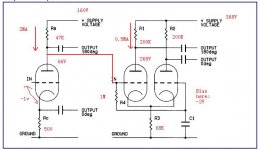
1 am going to build a EL34 PP amp using the circuit below
Page 19,20 of
http://www.lundahl.se/pdfs/claus_byrith/amplifier_30wpp.pdf
I have got a power transformer with following taps:
180v-170v-0v-170v-180v 300mA
3.15v-0v-3.15 5A
3.15v-0v-3.15 3A
0-50v 100mA
Due to direct couple from input stage(Using ef86) the cathode voltage in the driving+phase inverting stage(ECC83) may be quite high. Is it necessary to rise the potential of heater supply line of(ECC83) to avoide flash in cathod?
The 3.15v-0v-3.15v 5A heater is reserved for EL34 as I know that it is desirable to have separate volatge supply for power tube heater(high current) and line/driving stage heater(low current). If I raise the potential of the remaining 3.15v-0v-3.15v 3A heater for ECC83 and EF86 to a level close to cathod voltage of ECC83, the potential of heater line may be too high compared with the cathod of EF86.
Can anyone suggest any solution for this situation.
Thanks
Not sure I understand the problem. The schematic shows that the design uses just one 6.3V winding centered around ground for all of the tubes, so you have a working solution by just referencing both your LV windings to ground. Do you think this is a latent defect in the design? Have you changed something in the design you haven't mentioned? Or do you just want to improve upon the design?
vangogh-hk
In the Mullard circuit(s) the cathode/heater voltage is within the rating for the ECC83. But if you still want to bias up the filament voltage and stay away from the maximum for the EF86 of 100V, +40 to +50V (even 20V may be beter!) would be just about ideal and as an added benefit you would be biasing off the cathode/heater diode of the EF86 and may lower the heater/cathode hum of the EF86. 😉
Cheers
Wayne
Thanks Wayne,
I have another question that if I am going to use this EL34 PP amp with my Ground Grid (GG) pre amp, did I need to modified the EF86 input stage circuit.
Thanks
I have another question that if I am going to use this EL34 PP amp with my Ground Grid (GG) pre amp, did I need to modified the EF86 input stage circuit.
Thanks
I have another question that if I am going to use this EL34 PP amp with my Ground Grid (GG) pre amp, did I need to modified the EF86 input stage circuit.
Depending on the gain of your GG pre-amp and the output level of your input sources; as the gain of the Mullard 5-10 and 5-20 is pretty high to begin with, you could strap the EF86 as a triode. As a result it will lower the input noise (partition noise) and lower the output impedance and distortion of the EF86. Downside: It will increase the miller capacitance, but it won't be of much concern IMO. Some people highly prefer a triode over a pentode as the first stage of amplification. 😉
Cheers
Wayne
Thanks,
I am already using the scheme in page19 (The 4-30)with triod connected EF86 without cathode bypass cap. If Specification of my DIY GG Pre amp which is going to be connected to this power amp is:
Gain: 12 dB.
Max Signal Out: 20 volts RMS.
Output Impedance: 200 ohms.
Input Impedance: 50 k Ohms
Should I modified the EF86 stage or the Ecc83 stage (e.g. change to 12AT7) or just let it be.
Thanks
Should I modified the EF86 stage or the Ecc83 stage (e.g. change to 12AT7) or just let it be.
IMO, changing from the 12AX7/ECC83 to the 12AT7/ECC81 in the phase splitter position makes LOTS of sense. The net harmonic distortion spectrum of PP "finals" combined with a 'T7 driver is a PLEASING 2nd>3rd>4th, etc. Also, the 'T7 has a high gm. That makes it superior to the low gm 'X7 as a LTP splitter/driver. High gm types are LESS likely to slew limit. Always use grid stoppers with high gm types.
FWIW, I'd try a triode wired EF86 in the voltage gain position, as your line stage has appreciable gain. If it turns out you need some more gain, switching from the EF86 to a section of a 5965 is an option.
Thanks
If I replace the ECC83 with 12AT7, do I need to adjust the value of other components in the circuit?
Thanks again
If I replace the ECC83 with 12AT7, do I need to adjust the value of other components in the circuit?
Thanks again
If I replace the ECC83 with 12AT7, do I need to adjust the value of other components in the circuit?
Probably. A good "spot" for the 'T7 is 200-220 V. on the plate and Ib = 3 mA.
Eli
Could you tell me what value of resistor should be used on the plate (instead of 150k + 47k VR)and cathode (instead of 82K) of the 12AT7 then?
Thanks
Could you tell me what value of resistor should be used on the plate (instead of 150k + 47k VR)and cathode (instead of 82K) of the 12AT7 then?
Thanks
Need help for EL34 PP project
Some more questions about my EL34 project:
From the scheme in page 19 of
http://www.lundahl.se/pdfs/claus_byrith/amplifier_30wpp.pdf
1. What value of volume control VR should I use?
2. I got some 1u 630v MKP cap in hand, can I use it in the phase splitter (replace the 0.47u under the Ecc83, any bad effect?)
3. What type of 47K VR (carbon, wire wound, conductive plastic, etc. and what rating) should I use between the two 150K resistor beside the Ecc83?
4. What type of 22K VR (carbon, wire wound, conductive plastic, etc. and what rating) should I use in the bias supply for EL34s?
Could anyone tell me what value of resistor should be used on the plate (instead of 150k + 47k VR)and cathode (instead of 82K) if I replace the Ecc83 with the 12AT7 then?
Thanks for your help
Vangogh,
To agree, the phase inverter here is not the place for an ECC83. I would agree entirely with the use of an ECC81. I did not read through all of the Byrith document, so I will suggest provisional values for the resistors. If you can adjust the (triode-connected) EF86 bias such that it gives an anode voltage of about 130V, then the ECC81 common cathode voltage would be about 135V. If you use a 47K resistor there (1W) it will give you about 1,44mA Ia in each of the ECC81 triodes. Using anode loads of 82K with a 10k - 20K balancing pot should leave you with about 270V on the anodes. (Don't make the balancing pot bigger; slider contact might begin to influence performance, and I did not experience that ECC81 triodes differ that much.) The EF86 makes a very good triode, unless you must save by using half of a double triode as input tube for 2 channels.
With regard to your other questions:
1. I do not notice a volume control in the diagram on page 19, but presume you mean an input control. I would not go above 100K, to keep the Miller capacitance of the EF86 out of the picture. Most pre-amps should be able to drive that comfortably. If possible go lower, about 20x the output impedance of your pre-amp.
2. The 1uF cap would do no harm, but it would simply be unnecessary - you already have a -3dB frequency there of below 1 Hz! You could in fact go as low as 0,1uF.
3. As said a lower value for the pot, preferably a cermet trimmer or such. Not carbon. Wire-wound is fine, but it might be bulky.
4. The same for the bias supply (The cermets I know of are usually 1/4W; 1/2W would be better.)
These are values I have used and prefer; other variations are possible in the experience of other members.
Regards.
Vangogh,
I had another look at that p.19 circuit and only now noticed something else that worries me (it is 2 AM here, perhaps I should wake up!)
I have a problem with the fixed bias circuit. If I read correctly, there is a 22K pot from -80V to common, i.e. you are in danger of adjusting the bias right down to zero! If there are no further comments about this elsewhere (I did not read all the pages), I would suggest a safer circuit. (I am now going to suggest values off my head and hope you can check beforehand.)
I would change that pot (that is the one from -80V to common) to 10K. At the common end I would insert a serie resistor of 22K between pot and common. At the other end, from the pot to -80V, I would insert a serie resistor of 10K. That would give you a minimum voltage of some -35V and a maximum of about -50V over the pot. That is safer than to have the danger of going to 0V. These voltages would be influenced by where the tap (slider) to the 47Ks + the other 22K balancing pot is, but you should be in the right region. As said, off my head, but I believe the required EL34 bias lies somewhere at -40V. I hope you get the general picture, and that this helps.
Regards.
I am doing this now
But it's hard to get balance from the ECC83 with EF86, I think the designer wanted to get 80V from the EF86 output, I try many times, but failed.
Is there anyone have done this sucessful? Can you show the data of all parts of volta with this circuit diagram in practice?
But it's hard to get balance from the ECC83 with EF86, I think the designer wanted to get 80V from the EF86 output, I try many times, but failed.
Is there anyone have done this sucessful? Can you show the data of all parts of volta with this circuit diagram in practice?
Burdary
How many volt did you get from the ef86.
I think this volatge need not be very accurate if you can roughly get your required bias volatge at the ecc83.
How many volt did you get from the ef86.
I think this volatge need not be very accurate if you can roughly get your required bias volatge at the ecc83.
Re: I am doing this now
What exactly do you mean by "balance from the ECC83"? If you are talking about electrode voltages, I could not find anything given by Byrith - unfortunate.
In the absence of that, if you use 80V on the EF86 anode, a rough calculation shows that the ECC83 anode voltage will be about 318V, giving only 0,5 mA anode current. To my mind, driving an EL34, this would necessitate a maximum signal anode voltage of almost 360V, which is rather low and I expect quite some 2nd harmonic distortion.
On the other side of things, an ECC83 do not like working with an anode-cathode voltage of much lower than 120V (don't have my data sheets right now). That would need some 135V maximum on the preceeding (EF86) anode. I am guessing a little here, being away from home; others could correct. With all respect to Claus Byrith, I still prefer an ECC81 in this application, i.e. for driving EL34s. (ECC83 has too high an output impedance; effect of EL34 input capacitance, etc.) If you could look up the 520 circuit (similar application), some of them give d.c. voltages for the phase inverter.
Regards.
burderly said:But it's hard to get balance from the ECC83 with EF86, I think the designer wanted to get 80V from the EF86 output ......
What exactly do you mean by "balance from the ECC83"? If you are talking about electrode voltages, I could not find anything given by Byrith - unfortunate.
In the absence of that, if you use 80V on the EF86 anode, a rough calculation shows that the ECC83 anode voltage will be about 318V, giving only 0,5 mA anode current. To my mind, driving an EL34, this would necessitate a maximum signal anode voltage of almost 360V, which is rather low and I expect quite some 2nd harmonic distortion.
On the other side of things, an ECC83 do not like working with an anode-cathode voltage of much lower than 120V (don't have my data sheets right now). That would need some 135V maximum on the preceeding (EF86) anode. I am guessing a little here, being away from home; others could correct. With all respect to Claus Byrith, I still prefer an ECC81 in this application, i.e. for driving EL34s. (ECC83 has too high an output impedance; effect of EL34 input capacitance, etc.) If you could look up the 520 circuit (similar application), some of them give d.c. voltages for the phase inverter.
Regards.
IMHO, those who suggested ECC81 for the splitter are correct. Also, if you want to make a further improvement in the splitter, give it a CCS tail. This will really balance it properly. There is enough voltage between the splitter cathodes and ground for an SS CCS, so you won't need a negative supply for that purpose (although there is a negative supply anyway in Mr. Byrith's design; heck, with that negative rail, you could even use a pentode CCS - my favourite!)
Thank your for your reply
In my opinion, ECC83 here maybe better than ECC81, because it consider to drive the EL34, as we all know, low current and high voltage in electronic tubes can make better sound.
My EF86 anode was 80V and ECC83 bias volatge is 2V, and the ECC83 two anodes could not get balance, one side had 50V high than the other. so it worked badly.
In theory, the grid voltage connect with 1UF capacitor to the ground may high than the other grid, but I got the opposition result, which voltage to the ground is low than the other grid, I had no idea how to deal with it.
I want to redesign it, and I will put my design picture here, I hope all of you can give me some advices. Thanks!
A good news is that we have a long holiday, I will have more time to deal with it.
- Status
- Not open for further replies.
- Home
- Amplifiers
- Tubes / Valves
- Question about DIY EL34PP amp