Re: How about this?
You need to make a little change , the output connected to R1 must be 0 deg. , the other from R2 must be 180 deg.
burderly said:
Any advice and comments are highly appreciated!
You need to make a little change , the output connected to R1 must be 0 deg. , the other from R2 must be 180 deg.
As I am doinig a project based on the Byrith circuit I very much appreciate all the inputs in this thread. I will follow the original schematics to begin with as I soon have all the parts inhouse. The chassie is not finished yet so the soldering has not started. For my part it is a -learn about tube amps - project. A question is of course if I in my finished amp need to take some precautions based on Johans P.`s comments on the bias network. What happends if you adjust bias down to zero?
If you adjust bias towards zero, the plate and screen currents will rise and, before you reach zero bias, the tube elements will melt (equivalent to having too low a cathode resistor in a cathode-bias arrangement).
It is normal, in designing a practical fixed-bias circuit, to use a simple network of fixed resistors either side of a potentiometer so that the variable bias adjustment range is both safe and useful. I am suspicious of bias circuits that do not have this inbuilt safeguard, because they suggest that the designer himself is not a very practically-minded person. Vanderveen's designs are typically like that, too.
It is normal, in designing a practical fixed-bias circuit, to use a simple network of fixed resistors either side of a potentiometer so that the variable bias adjustment range is both safe and useful. I am suspicious of bias circuits that do not have this inbuilt safeguard, because they suggest that the designer himself is not a very practically-minded person. Vanderveen's designs are typically like that, too.
Dear all,
I am very happy to see more people interested in this project. So that we can share our experience. I have just finish the project and are now enjoying the music. It sound very good compare to my existing cheap cheap low power gear.
".....to use a simple network of fixed resistors either side of a potentiometer so that the variable bias adjustment range is both safe and useful"
In my case I use a 12k resistor between a 15k potentiometer and ground to prevent the bias from getting to zero volt.
"....My EF86 anode was 80V and ECC83 bias volatge is 2V, and the ECC83 two anodes could not get balance, one side had 50V high than the other. so it worked badly"
I think you should check your ECC83 first to ensure the two triod inside are match. And then check your 22k potentiometer for AC balance.
Here is the reading in one of my channel to see wheather it is helpful to you.
EF86: B+=169v, V-plate=74v,bias=1v
ECC83 left: B+=418v, V-plate=335v, vk=76v, Vg=74v
ECC83 right: B+=418v, V-plate=336v, vk=76v, Vg=67v
EL34 upper: B+=453v, vbias=-36v
EL34 lower: B+=453v, vbias=-38v
Regards
Thanks for the advice on bias - I will look into it. I do not think I will be up and running until christmas. The measurments is helpful, of course. This is my first project and I hope to get someone with a scope to help me adjust the amp when it is finished.
Just two more things, if I may:
One must be careful about the measurement of the ECC83 grid voltages. Even with a 10M impedance DVM, application of the meter will slightly change the voltages. The second of Vangogh-hk's measurements (74V) will be close to reality, but the third line (Vg=67V) illustrates what I mean. This voltage cannot exist with both anode voltages as close as they are; it was drawn down by the meter; the 336V anode voltage would not exist with the meter attached - in fact the ECC83 would be close to cut-off then.
This does not matter. The (lower impedance) dual cathode voltage is the better indicator of conditions, and if desired to be known, subtract the EF86 anode voltage or better still, measure the grid bias between ECC83 cathode and EF86 anode directly (with care where the meter leads go so as not to generate oscillation). ECC83 balance can be seen in the anode voltages; in this case quite a good ECC83! (Sadly, units in twin triodes can differ by as much as 15%.) But is is wise to always keep the effect of a meter in mind.
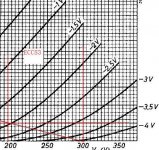
Then I am still worried about the ECC83 operating conditions. I am on record that I do not want to criticise a fellow designer's work unduly, but 83V over a high resistance anode load for driving an EL34 up to almost 40V peak signal is too low - sorry. I do not now have the circuit in front of me, but can recall that the EL34 grid resistor is not all that much higher than the ECC83's RL. These two are in parallel, and when the composite AC load line is drawn on ECC83 graphs, it will show that that stage goes very close to cut-off with full signal, with the penalty of severe 2nd harmonic distortion.
There is 259V static anode-cathode voltage over the ECC83, which can advantageously be dropped to 200V. Again not having graphs in front of me, it would look as if 98V on the EF86 anode will give about 100V on the ECC83 cathodes and 300V at the anodes. (The EF86 anode voltage could be adjusted by slightly increasing the cathode resistor.)
Not to belabour this point - building the amplifier uses your money, it is your decision, but a change that I will recommend.
Regards.
One must be careful about the measurement of the ECC83 grid voltages. Even with a 10M impedance DVM, application of the meter will slightly change the voltages. The second of Vangogh-hk's measurements (74V) will be close to reality, but the third line (Vg=67V) illustrates what I mean. This voltage cannot exist with both anode voltages as close as they are; it was drawn down by the meter; the 336V anode voltage would not exist with the meter attached - in fact the ECC83 would be close to cut-off then.
This does not matter. The (lower impedance) dual cathode voltage is the better indicator of conditions, and if desired to be known, subtract the EF86 anode voltage or better still, measure the grid bias between ECC83 cathode and EF86 anode directly (with care where the meter leads go so as not to generate oscillation). ECC83 balance can be seen in the anode voltages; in this case quite a good ECC83! (Sadly, units in twin triodes can differ by as much as 15%.) But is is wise to always keep the effect of a meter in mind.
Then I am still worried about the ECC83 operating conditions. I am on record that I do not want to criticise a fellow designer's work unduly, but 83V over a high resistance anode load for driving an EL34 up to almost 40V peak signal is too low - sorry. I do not now have the circuit in front of me, but can recall that the EL34 grid resistor is not all that much higher than the ECC83's RL. These two are in parallel, and when the composite AC load line is drawn on ECC83 graphs, it will show that that stage goes very close to cut-off with full signal, with the penalty of severe 2nd harmonic distortion.
There is 259V static anode-cathode voltage over the ECC83, which can advantageously be dropped to 200V. Again not having graphs in front of me, it would look as if 98V on the EF86 anode will give about 100V on the ECC83 cathodes and 300V at the anodes. (The EF86 anode voltage could be adjusted by slightly increasing the cathode resistor.)
Not to belabour this point - building the amplifier uses your money, it is your decision, but a change that I will recommend.
Regards.
Dear Johan
Thank you very mcuh for your recommendation. It is very useful and constructive and I will try it (of couse at a later time; give me some time to enjoy my master piece as it still sound good right now). Acutally the EF86 I am using is a 6x32pi(Russian old tube) and I am going to buy a better EF86 (e.g. TFK, Mullar e.g.)
Do you think that the plate volatge of EF86 and the anode-cathod volatge of ECC83 will change if I use a new EF86.
Regards.
vangogh-hk said:Dear all,
EF86: B+=169v, V-plate=74v,bias=1v
ECC83 left: B+=418v, V-plate=335v, vk=76v, Vg=74v
ECC83 right: B+=418v, V-plate=336v, vk=76v, Vg=67v
EL34 upper: B+=453v, vbias=-36v
EL34 lower: B+=453v, vbias=-38v
Regards
Thank all of you to discuss it with me, especially the guy who provided the practical data to us.
I had tried a few circuits with EL34 PP, and could not get a good sound one, so this time I made a decision to do it well. I think theory is very useful to us when we put it into practice, especially when we adjust balance with the current and voltages. I found many of them here who have abundant theory knowledge and experiences, which is the reson I like to come here.
Sometimes, I want to indicate something clearly, but I can not get the right words, because we seldom to use English in our daily life. But I will try my best to express clearly.
vangogh-hk said:Do you think that the plate volatge of EF86 and the anode-cathod volatge of ECC83 will change if I use a new EF86.
Whew!
One cannot really say, what with the sometimes tolerance in the characteristics of present-day tubes. I have no experience of the 6X32. Perhaps a practical suggestion: Now that we know what the electrode voltages must be, be ready to adjust the EF86 cathode bias resistor! That would get everything else right becasue of the dc connection between EF86 and ECC83. I really hate to say this, but one might in future need to make a small part of that cathode resistor (was it a 470 ohm?) adjustable (horrible idea). I am afraid I have experienced up to 20% variation in (new) EF86 currents these days. The sample was about 20 as replaced in Quad IIs I refurbished.
Then Burderly,
To me it says (or should) that sites like these are not about language. Better if one can express what one wants to say, but one can always ask again. I cannot speak Chinese at all!
Regards.
- Status
- Not open for further replies.
- Home
- Amplifiers
- Tubes / Valves
- Question about DIY EL34PP amp