Hi folks,
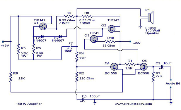
This is my first post on the forum. My question is about the circuit design on this amplifier. It use a Darlington output but the strange on the design is the absence of a emitter current resistor on 2N3904 differential input stage.
Is the design OK or should be modified ? What I don´t understand is the negative feedback on 2N3904 differential stage. Any suggestions are welcomed !!
The design is wrong. As it stands both of the 2N3904 will short out the two rails and (probably 😉) violently explode.
The input side has a 4k7 to rail. Both have 10 Ohms to rails. Would work if feedback 3904 collector was connected to 3906 collector, rather than emitter.
Doc
Doc
Last week I repaired a guitar amp that use another circuit schema. Because it was repaired wrong and with missing components I decided to rebuild from scratch using this design. Only I replaced 10uf input capacitor with 470 nf to avoid very LF feedback that can damage the speaker and relaced BC 558 with BC556 (matched properly measuring the HFe). It works great but quiescent current set a .022 A (22ma) leads to some crossover distortion at very quite volume. Original guitar amp design use NPN types for the input diff amp and pre exciter (BC549/559), maybe not recommend from my point of view due the collector emitter breakdown voltage of only 45 volts (BC 556 / BC546 reach 65 volts).
The idea was to find a tested circuit reference using NPN types for the diff amp stage.
Previous circuit with wrong schema can be found here -> Power Amplifiers
The idea was to find a tested circuit reference using NPN types for the diff amp stage.
Previous circuit with wrong schema can be found here -> Power Amplifiers
Last edited:
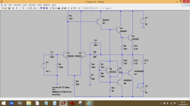
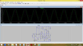
This is a working version version of the amp in post #1 The outputs can be darlingtons, although I used separate drivers here. R3 can be a 100k preset and used to trim the output to zero volts DC.
Its not a great circuit but it can be improved. Replacing R3 with a current sink would be a good start.
Its not a great circuit but it can be improved. Replacing R3 with a current sink would be a good start.
Attachments
This is a working version version of the amp in post #1 The outputs can be darlingtons, although I used separate drivers here. R3 can be a 100k preset and used to trim the output to zero volts DC.
Its not a great circuit but it can be improved. Replacing R3 with a current sink would be a good start.
Indeed this is a better design. Perhaps you could keep R3 as it is and add a preset around 5k-10k for a more precise adjustment of the DC offset at the output and increased stability over the years due to the wiper oxidization. The current sink is also a good practice and perhaps R5 could be replaced by a bootstrapping circuit.
Yes, you could certainly do both those things. The design could be tweaked extensively, its really how far the OP would want to take things.
Thanks for the new circuit and how to improve it. The idea is to build a discrete amp with minimal components. IC devices are limited in Vcc and current output triggering the on chip protections at maximal ratings. For example the LM7294 at +30/-30 Vcc will trigger the on chip protection with a loudspeaker impedance of 4 ohms. A discrete amp configuration without current and short circuit protections is a better choice for the guitar amp because it use +42/-42 Vcc and a 4 ohms speaker.
I will try to build the circuit using darligntons removing R9 and R10.
I will try to build the circuit using darligntons removing R9 and R10.
OK 🙂 Remember to make R6 variable to set the bias current and initially have it set to max resistance which gives lowest current. A 2k2 preset should be OK.
keep the rails at 30 volt max 45 i s way out transistor specs ...
Yet again the famous John fisher amplifier
Very explosive !!!
Yet again the famous John fisher amplifier
Very explosive !!!
- Status
- Not open for further replies.
- Home
- Amplifiers
- Solid State
- Question about circuit design