Screen resistors seem overly large to me. You can put 100 ohm or 150 ohm resistors in place of your current 1.5K resistors and be just fine.
The reason for the large screen resistors was to drop the voltage by 50V or so since the 807 can't take a lot of screen voltage. Depending on the OPT I use I may or may not run UL.
How would one go about calculating the screen current to get that resistor value correct?
The 807 is a tough little tube and I bet it wouldn't even flinch if you just ran it at 410V with smaller screen resistors. Large screen resistors are going to pull down the screen voltage quite a bit at max power which isn't what you want.
Another option however is to run the output stage in pentode mode. It's a relatively trivial matter to design a power supply with screen tap off that would deliver (approx) 300V screen voltage you'd need to optimize for a 410V plate supply and 6.6K primary. I think this would be the cleaner approach. There are several ways to do this. The approach I'd look at is a power mosfet with a 300V voltage reference on the gate.
Another option however is to run the output stage in pentode mode. It's a relatively trivial matter to design a power supply with screen tap off that would deliver (approx) 300V screen voltage you'd need to optimize for a 410V plate supply and 6.6K primary. I think this would be the cleaner approach. There are several ways to do this. The approach I'd look at is a power mosfet with a 300V voltage reference on the gate.
IRF820 with six 51 volt zeners in series (bypassed witha ~10uF or so cap) as a reference, run a pot across the top zener for some adjustment range, and feed this voltage to the mosfet gate via a largish resistance (470k or so) and run a 1~10uF cap to ground, this will give you a super stable and quiet supply with some adjustment range to dial everything in. I've got one of those with five 1N5262 zeners and a pot for the screen supply on my EL86 amplifier, it works fantastic, and is cheap to implement. Highly recommended.
Has anybody used 410V B+ and Ultra Linear on 807s? How long did the 807s last? screen 300V max, pentode mode screen 400V max, Ultra Linear mode Ultra linear mode should be somewhere between those 2 values, 300V / 400V.
What was wrong with using the coupled cathode phase splitter? It has low to medium gain, and has an unused grid to apply negative feedback to. A negative voltage and IXYS or other current source is all that is required.
Here is an example: coupled cathode phase inverter schematic - Google Search
The right hand grid is where the negative feedback is applied. You can use many other current sources, and use 6J5 tubes (more current, and different plate load resistors), etc.
You could use the cathode coupled phase invertor, plus what kward suggested: Pentode mode and the 300V screen B+.
Last edited:
Has anybody used 410V B+ and Ultra Linear on 807s?
How long did the 807s last?
Yes, even 450 V. No problems of any sort within several years of regular use. The highish plate and screen voltage is not causing tubes to wear out, but excessive dissipated power is.
What would be the advantage of the coupled cathode phase splitter over the single 6J5 cathodyne configuration? I'm not opposed to it, as 6J5s are cheap and beyond that I have some other tubes in stock that probably be suitable. The 6L6 build I'm working on now uses an LTP, and I thought this could be an interesting comparison.What was wrong with using the coupled cathode phase splitter?
It has low to medium gain, and has an unused grid to apply negative feedback to.
A negative voltage and IXYS or other current source is all that is required.
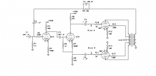
Here's a slightly more readable schematic. I added a preamp stage using a 6C4. I have yet to decide on a power transformer. I do have a HK Citation II power transformer sitting here, but I figured that I should save that for something that can use it to its full potential. Would it be better to connect the feedback circuit to the cathode of the 6C4 instead of the grid?
Attachments
Last edited:
The cathode coupled differential pair, a.k.a long tailed pair offers some gain (typically about half of what you'd get if connecting the tube in common cathode mode and under the same bias and power supply conditions), whereas the cathodyne a.k.a split load inverter offers no gain.
The cathode coupled differential pair can swing more volts than the cathodyne under the same power supply conditions and using the same tube type. (This wont be an issue though when driving the 807's in your design).
The cathode coupled differential pair offers equal output impedance on both outputs while the cathodyne does not, although this is usually not significant in AF power amp designs.
You will have slightly more gain with the voltage gain stage coupled to the split load inverter vs just the cathode coupled diff pair if using 6J5's all around. The number of triodes used in either approach will be equal. Feedback requires gain to do its work, so if you want to use more feedback, then the split load inverter approach will be slightly advantageous, although this really isn't significant either.
The feedback circuit needs a voltage divider to set the amount of applied feedback. In your latest iteration schematic the lower resistor in your feedback voltage divider is the 1Meg grid leak on the 6C4. It will be easier to set the feedback amount if you bring the feedback signal back to the cathode circuit of the 6C4. But I'd split the cathode resistance into a series connected 560R and 200R, with the 200R connected to ground, and bring the feedback signal to the junction of those two resistors. The lower resistor in your feedback voltage divider will then be 200R, and your Rfb will probably be in the 2k to 4k range, thus a much more "sane" value.
Last edited:
One more thing. As discussed you will probably want a negative voltage supply hooked to the tail if using just the cathode coupled diff pair. This could be the same supply as used for output stage biasing, if designed for it, which you're going to need regardless.
So either approach is doable with about the same level of complexity. It just depends on which approach you'd like to take.
So either approach is doable with about the same level of complexity. It just depends on which approach you'd like to take.
Last edited:
Would there be much of a difference in sound quality between the coupled cathode differential (LTP) and the cathodyne? Obviously this is hugely dependent on the situation.
I already have a pair of 6C4 tubes (assuming they test good... gotta get that Heathkit IT-21 tube checker working...). Difficulty/complexity/effort wise the two methods are similar, but I seem to see the LTP in a lot of newer designs... is there a good reason for that?
Any good suggestions for output trannies for this? I'm still working on my 6L6 amp with the Edcor transformers, so I haven't had a chance to hear them yet. I see old 7591 output transformers from Fisher 400s and Heathkit AA-100s go for not too much on ebay as well, or I could see what it would cost for Heyboer to wind some up. Other suggestions? I'd prefer not to spend a truly insane amount on transformers.
As far as the power transformer is concerned, I'm thinking I'll just pick up something off eBay. Maybe like a 350-0-350 @175 mA or thereabouts. I don't necessarily want to use a toroidal for this since I don't think it will match well with the whole grey vintage transmitter aesthetic I was thinking for this.
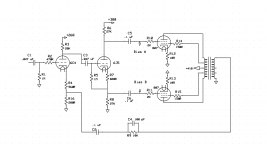
This what you were thinking with the feedback circuit by the way?
I already have a pair of 6C4 tubes (assuming they test good... gotta get that Heathkit IT-21 tube checker working...). Difficulty/complexity/effort wise the two methods are similar, but I seem to see the LTP in a lot of newer designs... is there a good reason for that?
Any good suggestions for output trannies for this? I'm still working on my 6L6 amp with the Edcor transformers, so I haven't had a chance to hear them yet. I see old 7591 output transformers from Fisher 400s and Heathkit AA-100s go for not too much on ebay as well, or I could see what it would cost for Heyboer to wind some up. Other suggestions? I'd prefer not to spend a truly insane amount on transformers.
As far as the power transformer is concerned, I'm thinking I'll just pick up something off eBay. Maybe like a 350-0-350 @175 mA or thereabouts. I don't necessarily want to use a toroidal for this since I don't think it will match well with the whole grey vintage transmitter aesthetic I was thinking for this.
This what you were thinking with the feedback circuit by the way?
Attachments
I think you have a solid design now and will provide the basis for a great sounding amp. Problem with the old stock output iron is nearly none of that iron has UL taps. If you want UL I think you'll have to settle for new production. Edcor or Hammond will deliver pretty good performance. Hammond 1650H or HA will work pretty well for this. It's been years since I've used Edcor outputs so I'm probably not the best qualified to comment on their PP iron.
Do consider Edcor for your power transformer. Their stuff is rock solid but sometimes they buzz mechanically. Fix that by popping off the end bells and wedging some strips of cardboard tightly between the bobbin and iron. 350 volt secondary might be a little high for 410 VDC delivered to the center taps, depending on how much voltage drop you have across your rectifier tube(s). A 340-0-340 would be about right for 410 VDC if using a 5AR4. Or a 310V secondary would be about right if using silicon rectification.
If this is going to be a two channel amp on a single chassis with one power supply powering both channels I think you will want a beefier high voltage winding, one that can source approx 400 mA. For my 1625 PP two channel amp, I custom ordered a power tranny from Heyboer since I needed 12.6V low voltage winding.
The split load inverter is a rock solid performer if you don't need to swing lots of volts (which you don't in this design). It offers naturally well balanced outputs and should not be underestimated in performance relative to the LTP. As I mentioned its biggest downside is no gain. People use the LTP if they need lots of volts swing, more gain, and it also affords the use of a CCS which is an easy way to automatically balance outputs. Nothing wrong with simple though, which the split load inverter is.
Last edited:
With a little careful thought, you could probably design this thing to eliminate the r/c coupling between first and second stage. You could also remove the input cap in the 6C4 grid circuit if you can guarantee there will never be any DC on the line from the source driving it. So that means you have only one r/c coupling in the entire amp. That will make it easier to get the amp stable when you add the feedback. It will be about as dead simple as you can make it.
For my 1625 PP two channel amp, I custom ordered a power tranny from Heyboer since I needed 12.6V low voltage winding.
What about a transformer from an old Tek scope? I've seen a few of them around for relatively little.
It might work, depending on specs. I've seen people build beefy bench power supplies out of them.
One of the ones I looked at had a pair of 113v windings (one at 430mA and the other at 740mA), plus a 161v winding at 360 mA. I was thinking that those three windings in series could work for the main high voltage supply. I think the model number was the 120-0307. And they have enough current in the heater windings to power just about anything.
Last edited:
That should work.
You know, with that Tek power transformer, if you used the three windings in series additive phase as you described, that would put you right around 475V B+ if using tube rectification (I assumed a 5AR4). That's pretty much ideal to load a 6.6K primary output transformer for PP AB1 operation if wiring the outputs in pentode mode with 300V screens. It would deliver approx 30 watts output as seen at the speaker terminals. Just a thought.
You know, with that Tek power transformer, if you used the three windings in series additive phase as you described, that would put you right around 475V B+ if using tube rectification (I assumed a 5AR4). That's pretty much ideal to load a 6.6K primary output transformer for PP AB1 operation if wiring the outputs in pentode mode with 300V screens. It would deliver approx 30 watts output as seen at the speaker terminals. Just a thought.
Regarding the regulated 300V screens, wouldn't 2x 0A2 tubes in series be a 300V reference? And of course I could totally use a bunch of zener diodes in series, but that doesn't glow purple.
Much of this will depend on the output transformers I end up with, and whether or not they have UL taps.
It just occured to me that I do have a PT from a Harman/Kardon Citation II. It's a little rough looking on the outside (been painted by multiple people who don't know how paint works) and it rattles when you shake it.😱
That said, it does work just fine and I probably can't sell it for much because it's a bit of a mess.
I am kind of digging this old Tek PT idea though. They're not very expensive and they look great, plus the HK transformer would require a voltage doubler to work for this. Thoughts?
Or you could use one 0A2 and some zeners depending on how much purple you want. VR tubes don't like a lot of capacitance strapped across their terminals though (check the 0A2 data sheet), whereas shunt capacitance on Zeners can be as much as you need to keep things quiet.
I am not familiar with the Fisher 400 output transformers.
I know that the 500 and 800 did use 7591 outputs in pentode mode. And the negative feedback from the secondary to the 12AX7 cathode worked well. It had a 12AX7 gain stage direct drive to a 12AX7 concertina splitter. I consider the 12AX7 to be a little bit wimpy for that kind of service, but . . . the output transformers had very good square wave response. We measured them out of circuit, with proper drive and load fixtures, and they were very good, nice phase and frequency response. Global Negative Feedback works much better with well behaved output transformers.
I am lucky, I have a pair of Fisher 500 / 800 output transformers. They have been used in other topologies, but I plan to use them in pentode mode again, with other output tubes and driver circuits.
- Status
- Not open for further replies.
- Home
- Amplifiers
- Tubes / Valves
- Question about building an amp without a preamp stage