Hi All,
I have build the Quasi Nmos200 power amplifier, it is almost finished! But I have some problems now, for some reason the fuses on the amplifier keeps blowing and the output FET's as well.
Specs:
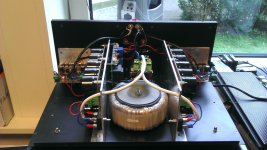
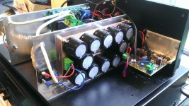
Power supply 2x38V 500VA toroidal transformer build to almost match this design the suggested power supply schematic for the Nmos350 from Quasi's diy page. The difference is that I have used 6x3300uF (= 19800uF) as decoupling instead of 2x10.000uF. Vout of the power supply is slightly higher then recommended 50V at 53V.
The suggested power supply can be found here:
Nmos350 / 500 - Quasi's DIY Audio Site
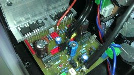
I have build the TO-220 version of the amplifier and have it mounted on a heat sink. I have used all the components specified by the schematic.
Nmos200 - Quasi's DIY Audio Site
Testing:
I have been listening to the amplifier through the line output of an old receiver and it sounds great, no hum and nice clear sound.
I have followed the instructions on Quasi's diy to set up the amplifier, which can be found in the construction guide of the Nmos350. And i have managed to achieve the specified values with in a few mV.
But when I connect the amplifier to load, everything seems to go wrong! I have been testing with a 4 ohm load by using an big potentiometer connected to the output of the amplifier. And on the input I have connected a function generator with 0 -1V amplitude and a 1 kHz sine wave as signal.
At around 100mV input the amplifier gives a 2.5V output, so an amplification of approx 25 times. The amplification rate is the same as I turn up the amplitude of the input signal until the amplitude hits around 750mv and the fuses blow.
So I guess my question is:
Am I testing it in a wrong way? Have anybody else have similar experiences? Or does anybody have a tip I could try?
I have build the Quasi Nmos200 power amplifier, it is almost finished! But I have some problems now, for some reason the fuses on the amplifier keeps blowing and the output FET's as well.
Specs:
Power supply 2x38V 500VA toroidal transformer build to almost match this design the suggested power supply schematic for the Nmos350 from Quasi's diy page. The difference is that I have used 6x3300uF (= 19800uF) as decoupling instead of 2x10.000uF. Vout of the power supply is slightly higher then recommended 50V at 53V.
The suggested power supply can be found here:
Nmos350 / 500 - Quasi's DIY Audio Site
I have build the TO-220 version of the amplifier and have it mounted on a heat sink. I have used all the components specified by the schematic.
Nmos200 - Quasi's DIY Audio Site
Testing:
I have been listening to the amplifier through the line output of an old receiver and it sounds great, no hum and nice clear sound.
I have followed the instructions on Quasi's diy to set up the amplifier, which can be found in the construction guide of the Nmos350. And i have managed to achieve the specified values with in a few mV.
But when I connect the amplifier to load, everything seems to go wrong! I have been testing with a 4 ohm load by using an big potentiometer connected to the output of the amplifier. And on the input I have connected a function generator with 0 -1V amplitude and a 1 kHz sine wave as signal.
At around 100mV input the amplifier gives a 2.5V output, so an amplification of approx 25 times. The amplification rate is the same as I turn up the amplitude of the input signal until the amplitude hits around 750mv and the fuses blow.
So I guess my question is:
Am I testing it in a wrong way? Have anybody else have similar experiences? Or does anybody have a tip I could try?
Attachments
Hi All,
I have build the Quasi Nmos200 power amplifier, it is almost finished! But I have some problems now, for some reason the fuses on the amplifier keeps blowing and the output FET's as well.
Specs:
Power supply 2x38V 500VA toroidal transformer build to almost match this design the suggested power supply schematic for the Nmos350 from Quasi's diy page. The difference is that I have used 6x3300uF (= 19800uF) as decoupling instead of 2x10.000uF. Vout of the power supply is slightly higher then recommended 50V at 53V.
The suggested power supply can be found here:
Nmos350 / 500 - Quasi's DIY Audio Site
I have build the TO-220 version of the amplifier and have it mounted on a heat sink. I have used all the components specified by the schematic.
Nmos200 - Quasi's DIY Audio Site
Testing:
I have been listening to the amplifier through the line output of an old receiver and it sounds great, no hum and nice clear sound.
I have followed the instructions on Quasi's diy to set up the amplifier, which can be found in the construction guide of the Nmos350. And i have managed to achieve the specified values with in a few mV.
But when I connect the amplifier to load, everything seems to go wrong! I have been testing with a 4 ohm load by using an big potentiometer connected to the output of the amplifier. And on the input I have connected a function generator with 0 -1V amplitude and a 1 kHz sine wave as signal.
At around 100mV input the amplifier gives a 2.5V output, so an amplification of approx 25 times. The amplification rate is the same as I turn up the amplitude of the input signal until the amplitude hits around 750mv and the fuses blow.
So I guess my question is:
Am I testing it in a wrong way? Have anybody else have similar experiences? Or does anybody have a tip I could try?
Amplifier works fine have build NMOS 200 and 300/500
all NMOS working with +/-85 V DC without any problems since 2 years
ok for +/-85 V you will need for PA 6 pair Mosfet output devices for full power
but for HI-FI amp is working with 1 pair IRFP460 @ +/-85 V
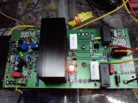
I can see faults in your PCB MJE 340/350 need heatsink and should be thermal coupled with driver on small heatsink
IS your MJE 340/350 pairs from diiferent manufacturer ? Check HFE
soem MJEs have HFE20 and from anather supplier have HFE 100 /160
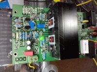
look picture my working NMOS pcb
Amber LED is for symmetrical clipping, grren LED replace string with 2 x 1n4148 in input stage
You have to much capacitors not necessary for low rail and for DC protectiom you can sue triac crowbar
Attachments
Last edited:
Short the input socket.
Measure the Vdc and Vac at the output with no load (open circuit) on the speaker terminals.
Measure the total amplifier supply rail currents.
Measure the output device currents.
Measure the Vdc and Vac at the output with no load (open circuit) on the speaker terminals.
Measure the total amplifier supply rail currents.
Measure the output device currents.
Short the input socket.
Measure the Vdc and Vac at the output with no load (open circuit) on the speaker terminals.
Measure the total amplifier supply rail currents.
Measure the output device currents.
It can be you have oscillation
If you have 2 mosfet pairs for each channel, disconnect 1 mosfet pair
and check again
- Status
- Not open for further replies.