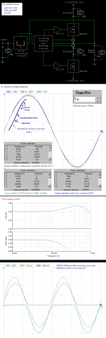
Using ordinary component in simulation (not realized yet) like IRFZ44, it has some good result, not as good as some best amp out there, but it is more than enough for only IRFZ44.
I just leave it here for a moment, and this result proof something about quasi design.
I just leave it here for a moment, and this result proof something about quasi design.
Attachments
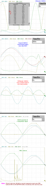
The plot showing 100kHz @ 45Vpkwith time/div = 2u
I am looking at the zero crossing of the input signal and comparing the rising against the falling.
In the rising version I can see that the currents in the two devices are very similar as they hand over to each other.
In the falling version I can see that the currents in the two devices are not at all similar.
Is this a picture of crossover distortion or is it cross modulation?
How can the circuit be tweaked to make the device currents more equal at the zero crossing of the signal? Which characteristic will improve? Crossover distortion of some other?
I have another advantage of using quasi, like the driver driving single mosfet instead of two, also it doesn't need to looking for match complementary (wide component choice), and more.
My pictures is proving that it could maintained well to not doing any dangerous collision even at high speed operation and using high(strong) error correction.
I post another picture (use mspaint to open so it could easily scroll up down and zoom large scale) contain simplified schematic and high frequency distortion simple picture.
There is another advantage of using quasi with this setting, the output waveform error will repaired with both side instead of one if it reach specific timing and error not repaired yet.
My pictures is proving that it could maintained well to not doing any dangerous collision even at high speed operation and using high(strong) error correction.
I post another picture (use mspaint to open so it could easily scroll up down and zoom large scale) contain simplified schematic and high frequency distortion simple picture.
Actually it could be improved by more precise and speed at control stage, but it is not really necessary improving audio amplifier to work at 100KHz.How can the circuit be tweaked to make the device currents more equal at the zero crossing of the signal? Which characteristic will improve? Crossover distortion of some other?
There is another advantage of using quasi with this setting, the output waveform error will repaired with both side instead of one if it reach specific timing and error not repaired yet.
Attachments
yes it help to minimize crossover distortion for high voltage operation (fast fall time)The plot showing 100kHz @ 45Vpkwith time/div = 2u
In the falling version I can see that the currents in the two devices are not at all similar.
Is this a picture of crossover distortion or is it cross modulation?
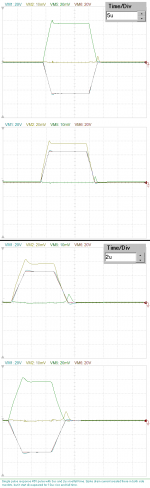
I do another test here, it showing the controller response in crossing maintenance.
The opposite mosfet start earlier at faster fall time (2us) than the slower (3us).
I cannot do this easily in non quasi. With non quasi design, I need to change its biasing voltage to do this.
Attachments
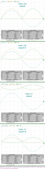
Speed up capacitors make it twice faster.
I am trying to make better small signal delay with placing some capacitors and it did well. Good small signal delay will be very useful for my power gain project, so I am going to tweak it instead of tweaking the other.
quasi + old HEXFET is really good stuff ?
I am trying to make better small signal delay with placing some capacitors and it did well. Good small signal delay will be very useful for my power gain project, so I am going to tweak it instead of tweaking the other.
quasi + old HEXFET is really good stuff ?
Attachments
Hi, another good news. This morning I am blowing a gecko many times until it death. It falling from the roof then trying to run but I catch it and kill it. Its big gecko.
The prophet says that blowing geckos and kill it, has great rewards. I am now kills 6 geckos total in my life.
The prophet says that blowing geckos and kill it, has great rewards. I am now kills 6 geckos total in my life.
- Status
- Not open for further replies.
- Home
- General Interest
- Everything Else
- QUASI is not that bad, really, (I post some proof here).