I have seen there are threads about designing Quasi Complementary amplifiers.
I wanted to try this.
So I started putting it together.
I decided to go simple.
I got an amplifier working.
Here is the result:

I wanted to try this.
So I started putting it together.
I decided to go simple.
I got an amplifier working.
Here is the result:
Last edited:

It is fine.220pF seems to be a high value for C4
I have a little bit concern about the thermal stability.
Can you explain to me ?I have seen there are threads about designing Quasi Complementary amplifiers.
I wanted to try this.
So I started putting it together.
I decided to go simple.
I got an amplifier working.
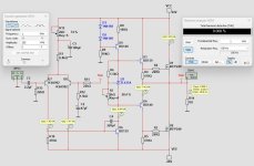
Here is the result:
View attachment 1470829
1, reason use D1
2, What difference ? if change bootstrap circuit ( R8,R9,C1) by constant curent source , (quality of capacitor) .
Yes.It is fine.
I have a little bit concern about the thermal stability.
But what should you do about it?
instead of TL431 put there BD139 (same position) and mount it at heatsink between IRF-sBut what should you do about it?
1. I really dont know. But I had seen other quasi amplifiers use such a diode.Can you explain to me ?
1, reason use D1
2, What difference ? if change bootstrap circuit ( R8,R9,C1) by constant curent source , (quality of capacitor) .
It is probably not necessary ... We could remove it and see what happens.
2. A current source is better.
How much better I dont know. We could test and see.
Thanks.instead of TL431 put there BD139 (same position) and mount it at heatsink between IRF-s
I will do that.
Here your two suggestion/questions in play.Can you explain to me ?
1, reason use D1
2, What difference ? if change bootstrap circuit ( R8,R9,C1) by constant curent source , (quality of capacitor) .
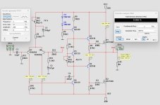
I removed D1.
I added a current source.
Now this did not change much in performance. But it feels better somehow.
Attachments
It is fine.
I have a little bit concern about the thermal stability.
Here you are.instead of TL431 put there BD139 (same position) and mount it at heatsink between IRF-s
Now BD139 is used for Vmultiplier and can be put unto heatsink.
This would make it more thermal stable.
Attachments
Thanks, @bordodynov
Can you add my latest circuit.
I have made some changes.
https://www.diyaudio.com/community/attachments/quasi-irfp240_06-bd139-jpg.1471054/
It should be noted that with the +/-24V supply this is a 20 Watt amplifier.
Is it possible to reduce supply or increase supply - Yes, I think so.
Say +/-20V or +/-30V.
The changes should be minimal for that.
Last edited:
Just by looking at it, should be good now.
Since you really like to play, few things to make it different and IMHO better:
Major change: replace LTP at input with single transistor and current feedback, that will make it faster. Than add opamp and global feedback, In another of your threads I mentioned it already... If you do this ; no problem to keep bootstrapping (even I don't think it is an issue anyway) and you can disregard all I wrote below:
For making this one as it is better as is, you can:
Have fun,
Drazen
Since you really like to play, few things to make it different and IMHO better:
Major change: replace LTP at input with single transistor and current feedback, that will make it faster. Than add opamp and global feedback, In another of your threads I mentioned it already... If you do this ; no problem to keep bootstrapping (even I don't think it is an issue anyway) and you can disregard all I wrote below:
For making this one as it is better as is, you can:
- current source also LTP, Vref can be the same from VAS current source (between D2 and R9). R15 pot is not needed in any case
- add another small transistor in-front U6 increasing VAS gain dramatically
- degenerate 2 input transistors in LTP
- read Douglas Self blameless amplifier articles through 🙂
Have fun,
Drazen
Thanks.
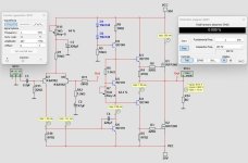
Does it look good?
I made a version with +/-30V supply.
There was a couple of small changes needed.
But it did go well - no problems.
+/-24V gives max 20 Watt output
+/-30V gives max 35 Watt output
THD at 1 Watt into 8 Ohm is in both supplies like 0.009%
Does it look good?
I made a version with +/-30V supply.
There was a couple of small changes needed.
But it did go well - no problems.
+/-24V gives max 20 Watt output
+/-30V gives max 35 Watt output
THD at 1 Watt into 8 Ohm is in both supplies like 0.009%
Yes @DrbuljJust by looking at it, should be good now.
Since you really like to play, few things to make it different and IMHO better:
Major change: replace LTP at input with single transistor and current feedback, that will make it faster. Than add opamp and global feedback, In another of your threads I mentioned it already... If you do this ; no problem to keep bootstrapping (even I don't think it is an issue anyway) and you can disregard all I wrote below:
For making this one as it is better as is, you can:
- current source also LTP, Vref can be the same from VAS current source (between D2 and R9). R15 pot is not needed in any case
- add another small transistor in-front U6 increasing VAS gain dramatically
- degenerate 2 input transistors in LTP
- read Douglas Self blameless amplifier articles through 🙂
Have fun,
Drazen
There are many changes I could do. For some improvement.
But as I mentioned in my first post I decided to make it simple.
With all your suggestions it would be another amplifier. Why don't you start a new thread and include all those things?
So, I will stay with my present amp.
It is good enough and should work well!!
🙂
- Home
- Amplifiers
- Solid State
- Quasi IRFP240 Amplifier