Nice results!
All very valid points and and great advantages with the quasi circuit.
http://www.ant-audio.co.uk/Theory/N-channel%20D-MOSFET%20output%20stage%20with%20improved%20linearity.pdf
Here is an article about possible variations of a n-channel fet push pull output stage.
Cheers,
Johannes
Why I like the quasi circuit.
1) Easily obtain a dominant 2nd Harmonic
2) Distortion easily tunable (by addition or cancellation of 2nd Harmonic)
3) Access to a variety of far more interesting mosfets that don't have complementary P Channel parts, eg SiC Jfets etc
4) Cost savings (buying in larger quantities generaly means cheaper pricing)
5) The table of results speak for them self (certainly not inferior)
All very valid points and and great advantages with the quasi circuit.
http://www.ant-audio.co.uk/Theory/N-channel%20D-MOSFET%20output%20stage%20with%20improved%20linearity.pdf
Here is an article about possible variations of a n-channel fet push pull output stage.
Cheers,
Johannes
With so many nice SiC devices becoming available, I thought it made a lot of sense to do a quasi complementary Firstwatt F4, I've modeled it with double die lateral mosfets but it should perform as well if not better with SiC devices.
Bias is 1.35A
I was too lazy to do a detailed bias circuit. I can do one if someone needs help with it.
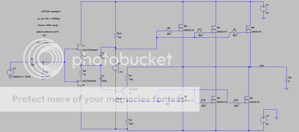
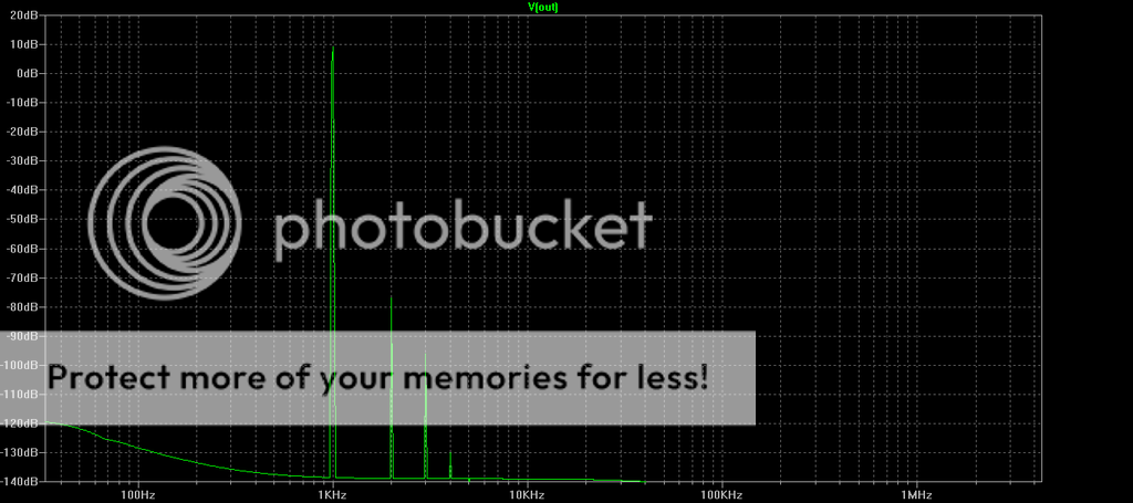
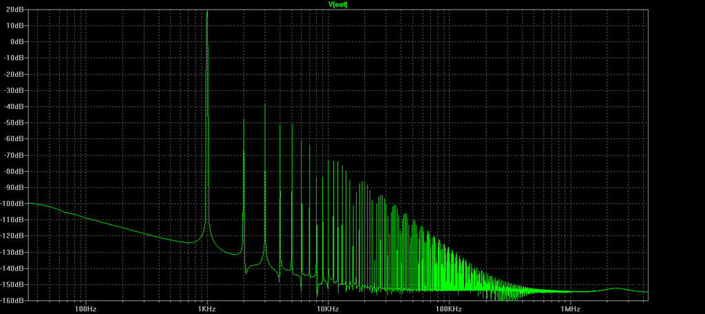
4Vpk into 8 Ohms
Total Harmonic Distortion: 0.005069%(0.005069%)
Will the upper bank of Mosfets benefit from being driven by the complement of BC556B?
Will the upper bank of Mosfets benefit from being driven by the complement of BC556B?
No not really the jfet buffer circuit is more than adequate to do the task, it already does this task in the regular complementary circuit.
Probably suggesting the best way to wire up in a real circuit, but for the purpose of a schematic there is no right way to draw it. It's just art work.
In this power buffer, positive signal goes through common drain output mosfets, negative signal goes through common source output mosfets. As you do not have negative feedback loop, negative output signal will have HIGHER impedance then the positive one.
No not really the jfet buffer circuit is more than adequate to do the task, it already does this task in the regular complementary circuit.
Thanks 2 picoDumbs. With so many interesting unisex [ZM's wording] devices, your successful approach of quasi-complementary can only broaden their scope of application. I'm thinking of the quasi complements of R100, R085, 2SJ28. and many others emerging in this forum.
Back to your original schematic of post#1. Will it possible to use in it only the front end complementary JFETs as drivers to the output as as follows. The N-channel JFET drives directly the upper bank of Mosfets. The P-channel generates the quasi-complement for the lower bank. The joint gates of the JFETs in the parent schematic needs to be broken, with appropriate voltage level shifting.
,-)
Yes, the most build as descripted.
Next step is to set drive-transes correct, than to differ DC and AC, AC to ground ... one psu or two psus ...
I would prefer ONE psu. And I would use the JFets as the complementary-step, as drivers - as descripted by Antoniel.
Or build a se. Much much better in my mind,-)
Back to your original schematic of post#1. Will it possible to use in it only the front end complementary JFETs as drivers to the output as as follows. The N-channel JFET drives directly the upper bank of Mosfets. The P-channel generates the quasi-complement for the lower bank.
Yes that was the original circuit which I tested, I'll happily show it here.
My memory is bad but I think I had issues of one of the jfets pinching off, I can't remember whether I resolved the problem. I'll retest it to see where I was at with it.
There are certainly a few ways you can do it.
Pico's Quasi vs F4
Pico's Quasi Circuit
Bias = 1.35A
14Vpk into 4 Ohms
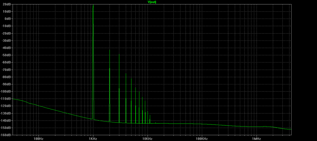
F4 Circuit
Bias 1.35A
14Vpk into 4 Ohms
Pico's Quasi Circuit
Bias = 1.35A
14Vpk into 4 Ohms
F4 Circuit
Bias 1.35A
14Vpk into 4 Ohms
But how does it sound? The result of "listening-measurement"-?
My experience: Just one complementary-step or a not-symmetric step sounds like a "folding screen" within the "soundstage", un-clean, broken, not-harmonic. The, a "looking-mesurement" does not show.
My experience: Just one complementary-step or a not-symmetric step sounds like a "folding screen" within the "soundstage", un-clean, broken, not-harmonic. The, a "looking-mesurement" does not show.
But how does it sound? The result of "listening-measurement"-?
My experience: not-symmetric step sounds like a "folding screen" within the "soundstage", un-clean, broken, not-harmonic.
Are you saying you don't like Mu Follower as well?
Hello Zen Mod
I'm thinking of using this adjustable reference for creating the bias circuit, adjusted for around 2V out.
http://www.ti.com.cn/cn/lit/ds/symlink/lm385-adj.pdf
What do you think?
I'm thinking of using this adjustable reference for creating the bias circuit, adjusted for around 2V out.
http://www.ti.com.cn/cn/lit/ds/symlink/lm385-adj.pdf
What do you think?
I'm using Z-5 iteration in Shunty ; great part
choose your poison - either that or Papa's TL431 solution ..... or resistor+LED or .........

choose your poison - either that or Papa's TL431 solution ..... or resistor+LED or .........
I'm using Z-5 iteration in Shunty ; great part
choose your poison - either that or Papa's TL431 solution ..... or resistor+LED or .........
TL431 is minimum of 2.5V which is on the high side of what I need. Hence the reason for adjustable LM385.
I am also considering a 2.5V LED or 2.5V precision reference with voltage divider for 2V output.
The LED is nice cause you know the bloody thing is working or not.
Hahahaha
Last edited:
Member
Joined 2009
Paid Member
But how does it sound? The result of "listening-measurement"-?
My experience: Just one complementary-step or a not-symmetric step sounds like a "folding screen" within the "soundstage", un-clean, broken, not-harmonic. The, a "looking-mesurement" does not show.
A very strange description, not sure I understand it ?
And I've listened to single ended amplifiers that sound very good
- Status
- Not open for further replies.
- Home
- Amplifiers
- Pass Labs
- Quasi Complementary F4 (inspired by SiC)